The B.B. in the title represents that this is from the archive of the late Bill Bently, who ran a flathead Q&A informational site before he passed away. All threads from this source will be titled using the B.B. identifier on this site. We’re archiving some of the threads, so that his work is not lost or forgotten and so they will continue to educate flathead enthusiasts for years to come.
THE SINGLE LUBRICATOR
(DETROIT-LUBRICATOR)
The Detroit-Lubricator carburetor used on early V8 engines (prior to 1934) was of the straight tube air vane type. This type of carburetor provides for an increasing amount of fuel as the volume of air entering the carburetor increases.
To service or adjust the carburetor correctly a complete understanding of it’s operation is essential.
The carburetor consists of two main units:
1. The Main Metering Unit – Comprises two air valves or vanes hinged at their upper ends and opening downward to admit air to the mixing chamber. These vanes have fingers which engage a central aspirating tube, lowering it as the vanes open. This aspirating tube is attached to a spring-loaded hollow stem carrying the fuel metering orifice in it’s upper end. An adjustable tapered metering pin projects into this orifice.
2. The Auxiliary Unit – Combines an auxiliary power jet, an accelerating pump (see Fig 3) and a priming passage for starting. The operation of the auxiliary unit is controlled by the registering of progressively located ports in the starting sleeve which line up with passages in the main body. The starting sleeve rotates with the choke lever; the pump plunger and piston move downwards as the throttle is opened.
To Start
To start a cold motor in cold weather, the choke control button should be pulled out to it’s limit and the throttle left in a closed position. This rotates the starting sleeve in the throttle body and lines up the primer passage with a hole in the wall of the starting sleeve, allowing fuel to be drawn into the manifold directly from the float chamber through the pump cylinder and hollow stem of the pump plunger. The throttle button must be pushed in so that a strong suction will be created below the throttle plate to draw fuel through the priming passage. Actually, the throttle plate will be opened slightly by the kicker rod when the choke button is pulled out, but this action is automatic and allows just enough air to pass the throttle to ensure good starting.
In extremely cold weather, starting can be aided by giving several quick strokes of the accelerator pedal after the choke has been pulled out. By this action the accelerating pump forces fuel through the primer passage into the manifold and so assists starting.
After the motor has started, push the choke control button part way in; the motor will then run on a richer mixture than normal. Experience will show the cirrect place to set the dash control, which will depend on temperature. As the motor warms up, the dash control should be pushed further in, and after the motor has become warm, the dash control should be pushed to the limit of it’s travel.
If the motor fails to start, check the position of the choke lever and see that the choke lever stops tight against the stop on the float bowl cover.
Normal Running
Fuel enters the carburetor float bowl through the strainer and float needle valve, and is maintained at constant level by the float and float needle valve. This level of should be 1 1/8″ to 1 ¼” below the top of the float bowl casting (see Fig 1).
Air enters the carburetor through the air inlet and opens the vanes as it passes downwards into the mixing chamber. The load of the metering spring on the metering valve, connected directly to the vanes, causes a partial vacuum to exist in the mixing chamber which draws fuel from the aspirating tube.
The quantity of fuel flowing is controlled by the tapered metering pin; at idle speed the vanes are closed and the metering pin almost fills the orifice in the air valve piston. As the vanes lower to admit more air, the metering valve also lowers, and the metering orifice becomes larger due to the the taper of the metering pin. This combination maintains the correct ratio of fuel and air for average running.
Maximum Power
For maximum power at any speed, a mixture richer than is necessary is required for running with the throttle partially open. The power jet A (see Fig 1) supplies the required extra fuel while the throttle is held open. At this throttle position, the pump plunger has travelled downward and has shut off the air vent to the power jet.; therefore, the suction on the discharge nozzle draws fuel from the pump cylinder up through the hollow stem of the pump plunger B (see Fig 1) and through the power jet into the mixing chamber.
At part throttle positions this power jet does not supply fuel, since it is vented to the outside air through the air vent hole in the upper part of the starting sleeve.
The quantity of fuel drawn from the power jet is controlled by the lower bleed holes in the starting sleeve.
For rapid acceleration, it is necessary to supply a momentarily rich mixture. This extra fuel is supplied by means of the accelerating pump.
A quick opening of the throttle causes a rapid downward movement of the pump plunger and piston, forcing fuel up through the hollow stem of the pump plunger and out through the discharge nozzle into the mixing chamber. The fuel in the pump cylinder is prevented from escaping back into the float chamber by the check valve in the bottom of the pump cylinder.
In general, for steady driving conditions up to 65 mph on level roads, the fuel is all supplied from the aspirating tube. When the throttle is opened suddenly, an additional charge of fuel is supplied from the accelerating pump; If the throttle is held open as for hard pulling or high speed, extra fuel continues to flow from the pump discharge nozzle through the power jet A.
ADJUSTMENTS
The Ford Motor Company recommends that all carburettors be adjusted with a vacuum gauge.
For a person not having a ford laboratory test set or a good vacuum gauge the following instructions apply.
To adjust idling speed.
The idling speed of the engine should be set by means of the throttle plate adjusting screw, to a speed equivalent to 5 mph in high gear.
To Adjust Metering Pin
Normally, only one adjustment of the carburettor is required, this adjustment being the fuel adjustment for idling. The metering pin is raised or lowered by screwing it into or out of the fuel orifice.
Be sure the motor is well warmed up, and there are no air leaks at the manifold (tighten the screws), windshield wiper or distributor vacuum line (tighten connections), then remove the carburettor silencer, adjust the metering pin carefully at idle speed.
Turning the pin clockwise moves the pin downward and makes the mixture leaner; turning it anti-clockwise increases the orifice and makes the mixture richer.
Screw the adjustment down until the performance of the engine indicates the mixture is too lean (speed will decrease) then turn it back slowly (allowing approximately 30 seconds at each setting to note the performance of the engine) until engine performance is again smooth (speed will pick up).
For initial setting for a cold engine, screw down the metering pin until the air vanes just start to open. Then turn back 3 ½ turns. Readjust after the engine has warmed up.
Throttle Plate Position for Starting

Unless tampered with, this adjustment will remain permanently correct. To check this adjustment, the carburetor assembly would have to be removed. Then insert a .020″ feeler blade (see Fig 1) and adjust the position of the throttle plate adjusting screw to maintain this throttle plate position when the choke lever is all the way to the rear and the starting sleeve lug is against the stop on the float bowl cover.
DUAL CARBURETOR (STROMBERG)
While different models of the dual Stromberg carburetor have been used on the various types of engine, enough similarity exists between them so that the person who understands the functioning of one can readily understand all of the various models.
Various jet and venturi sizes are used and the carburetors are not interchangeable.
In conjunction with dual manifolding, the Stromberg dual downdraft carburetor was first used on the 1934 cars.
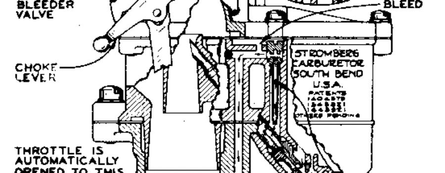
These carburetors are the plain tube type using an air bleed main discharge tube and a double venturi (see Fig 4). The secondary venturi is located above the primary venturi and, discharging below the point of greatest restriction in the primary venturi takes full advantage of the unbalanced pressures or the difference in pressure at the two ends of the secondary venturi, ie; atmospheric pressure at the upper end and the stepped-up vacuum at the lower end. In this the rate or speed of the air flow is greatly increased,
The dual carburetor can be considered as two carburetors built into one compact unit. There is a separate set of venturi tubes, main metering system, idle system, throttle plate and pump discharge nozzle for each barrel. These are fed with fuel by one accelerating pump, one fuel chamber and air through one air passage.
In the explanation that follows, one barrel is generally referred to, unless mentioned otherwise.

Idling Fuel Supply
The fuel from the carburetor bowl passes through the main metering jet into the idle tube as indicated by the arrows (see Fig 4). Air enters the fuel system at the idle air bleed and the mixture of fuel and air then travels downward to the idle discharge holes.
With the throttle stop screw set so that the throttle plate is wide open to a speed equivalent of 5 to 7 mph, as indicated by the dotted lines, the lower discharge only is subjected to inlet manifold vacuum. As the throttle is opened to increase the engine speed the throttle plate is moved above the upper idle discharge hole and fuel mixture discharges from both idle holes.
The lower discharge hole is provided with and idle adjustment. Turning out the needle gives a richer mixture and turning in, a leaner mixture. The idle adjustments should be set for the highest and steadiest vacuum reading. If the idle adjusters have been damaged with grooves in their valve points, they should be replaced in order to obtain a satisfactory adjustment.
Main Fuel Supply
The idle system is in operation up until approximately 18 to 22 mph, in which range the main metering system begins to function and furnishes fuel up to approximately 76 mph on 85 hp cars, and 70- mph on 60 hp cars. At this point the power jets also cuts in.
The fuel passes through the main metering jet into the main discharge tube where air is bled from the high speed bleeder into the fuel stream (see Fig 5). The air completely surrounds the main discharge nozzle and by entering it at several places forms bubbles to create an emulsion. This makes the fuel lighter in weight and more responsive to throttle valve movement. The fuel from the idle tubes is also taken into the main nozzle.
The main discharge tube is held in position by the main metering jet. The metering jet should be assembled securely in the body, but without excessive pressure, to avoid the possibility of causing the air bleed holes to close, resulting in too rich a mixture and poor low speed performance. The main nozzle was later designed to have two bleeder holes at the top instead of four.
NOTE: Do not attempt to remove a tight tube by applying pressure on the tip of the nozzle.
When assembling the main nozzle, place it so that the discharge opening is in a vertical position (see Fig 5),
Accelerating Pump
An accelerating pump directly connected to the throttle is provided to enrich the mixture slightly for rapid acceleration.
Fuel is admitted to the pump cylinder through the pump inlet check valve (see Fig 4). When the throttle is opened the pump moves downward and the pressure on the petrol closes the inlet check valve and opens the spring-loaded valve of the power jet, permitting the fuel to be forced out through the accelerating pump discharge jet and nozzle. Free movement is provided in the pump lever assembly to prolong the discharge of the fuel when suddenly accelerating from closed throttle to part open position.
Starting in 1936 the accelerating pump (see Fig 6) was made adjustable and should be changed for winter and summer. In the winter a greater discharge from the pump is desirable; this can be obtained by assembling the accelerating pump rod at the position farthest from the center of the throttle stem. Assembling the pump rod in the position nearest the center of the throttle stem cuts down the accelerating pump discharge and is the summer adjustment.
Power Jet
When the throttle is opened to a predetermined position the pump piston makes contact with spring-loaded valve of the power jet, holding the valve of the seat and permitting fuel to flow through the jet and the pump discharge nozzles. The additional fuel is required to enrichen the mixture for increased speed or operating under heavy load.
Choke
The choke valve is mounted on a floating stem that is located off-center in the air passage. A spring connects the choke control lever to the valve stem, so that when the choke control lever is in the part-closed position, the air rushing in forces the choke valve to open against the tension of the connecting spring. This, however, does not mean that the car can or should be continuously operated with the choke control in the part-choked position. With full choke the valve is held in a locked position by the control lever.

If the choke is held in full-closed position after the engine fires, a poppet valve or air bleeder is incorporated in the choke valve to supply air to keep the engine running. The opening of this poppet valve, and the rush of air flowing through it, makes considerable noise, which should attract the owners attention to the fact that the choke button is out and will continue to make this noise until the choke button is pushed in, either all the way or to a part-choke position.
When the carburetor is choked, the throttle valve is automatically open to the correct position for starting. For this reason it is neither necessary or desirable for the operator to pull out the throttle button when starting. In this position the throttle valve is directly opposite the upper idle discharge hole so that the stream of air passing around the throttle plate draws fuel for both the upper and lower discharge holes. In full choke position everything below the choke valve is subjected to inlet manifold vacuum and the bulk of the fuel is supplied by the main discharge tubes.


Was this article a help? Consider supporting the Flat-Spot by becoming a Premium Member. Members get discounts with well known retailers, a cool membership packet full of goodies and your membership goes toward helping us upkeep and expand on this great archive.


