The B.B. in the title represents that this is from the archive of the late Bill Bently, who ran a flathead Q&A informational site before he passed away. All threads from this source will be titled using the B.B. identifier on this site. We’re archiving some of the threads, so that his work is not lost or forgotten and so they will continue to educate flathead enthusiasts for years to come.
From JD, regarding generators, proper connections and grounding
Clarification is not debate, and it’s an area where a lot of people can be confused. Even me, about what was on what year. There are areas I am not real sure what it is I remember, and I need feedback and clarification if the “facts” I state are wrong. The other thing is, there are hard facts, and then there are opinions, and some shady ground in between. Some of this “stuff” I reference goes back to when I was 12 years old, having a father who could glean facts from manuals and believed everyone should be crystal clear after doing so. My next encounter was an auto shop teacher who was absolute on electrical theory, and a stickler for preciseness.
I had a lot of 6 volt experience, and barring modern 12V appliances attached, have had proof it is entirely adequate. I had a quarter stroker 49 Olds that was faultless on 6V, and those turkeys were hard starting.Cast brass soldered connectors and “tractor cables” were one answer, and a tractor battery another, as there was no “change to 12V” on the economic horizon. Eventually, 12V was a necessity for many reasons, and changing the regulator ONLY was the major necessity, as the 6V gen rarely was called upon to produce full amperage, but current regulators could be set back to protect it even then, not that we bothered. A major trick brush gens was to attach it to a regulator and set it for full output on the 3rd brush, setting the current regulator to protect the max output. That way the voltage regulator stopped overcharging the battery, but ensured a quick recovery to working voltage, but saved the change to a 2 brush gen. So easy now to use a self regulated alternator. Current regulators can only be adjusted with a shunt to discharge the battery, as full current can only occur at low battery, as the voltage regulator takes over as voltage rises at the battery.

Voltage drops from bad connections and neglected grounds can interfere with proper operation of voltage regulators, a good reason why we have regulators inside alternators today. Fords mostly have a ground strap between engine and frame, but they get discarded often. Even with that ground, a voltage regulator needs to see an accurate ground wire from gen frame to regulator frame, as it needs to know exact voltage not something maybe close. The regulator also depends on accurate battery voltage, demanding that the hot wire have adequate size to carry current and good enough connections to show exact bat voltage to the regulator. Whereas alternator bad connections will just get hot, generator bad connections result in a battery not being charged.
A word about positive ground versus negative ground is warranted. Ford always used internal ground fields, GM was always external ground fields. Either gen can be used for either positive or negative ground, provided you have the correct system polarity/correct field ground system regulator. That applies to either 6 or 12 volt. Current maximum of regulator can be set to match any generator size, so that’s not an issue with substitution. When you take the end plate off to replace brushes, note there is no internal connection from brush to field on Ford? That field current comes from the regulator, and the field grounds to the “other” bolt on the gen. Delco made both internal and external field ground regulators, so don’t be confused thinking it’s a GM gen because the regulator says Delco. ALL commercials were once positive ground too, so Delco had all the choices, once. That gives a choice of 4 regulators for a given generator, EVEN if the gen is 6V. Makes bolting on an alternator simple, doesn’t it? A simple voltmeter has many uses, to determine all the above.

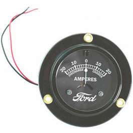
Ford ammeters were sometimes a metal loop the insulated wire passed through, that style cares not what voltage, but polarity reversal means either reading it backwards, or changing the direction the wire goes through the loop. It pays to be critical of insulation there, as that metal loop can eat through and ground that big wire, and it WILL get red hot! Two bolt ammeters are a simple switch of everything from one bolt to the other. The other Ford “device” you can do without is the circuit breaker as they always go bad eventually, and shut the lights off when you least expect. If you are concerned, put a fuse block in. Personally I never bothered. A grounded wire will manage to burn up the whole wire loom and miss the fuse 9 times out of 10, anyway. Like a fire extinguisher onboard, a fuse is never where you need it when the time comes.
Ford gauges are so varied that you can’t generalize about how to wire them. Changing polarity and 12V has to be dealt with on a car by car, preference by preference basis. Ignition resistors have a simple rule: The coil specs demand a resistor or not, ask the coil manufacturer. Mallory made every known system at one time or another, only the coil number will tell Mallory what resistor to use, or not.
–JD


