The B.B. in the title represents that this is from the archive of the late Bill Bently, who ran a flathead Q&A informational site before he passed away. All threads from this source will be titled using the B.B. identifier on this site. We’re archiving some of the threads, so that his work is not lost or forgotten and so they will continue to educate flathead enthusiasts for years to come.
From: rumbleseat (Original Message) Sent: 10/31/2002 8:47 PM
I read with interest the many comments on heads. My opinions and experience follow. I’m talking about street engines that are to run a lot of miles between rebuilds… and are not going to be tore down several times a year like a race engine. I believe in building them stout without a lot of trick stuff to increase longevity and reliability, but I want them to run hard too.
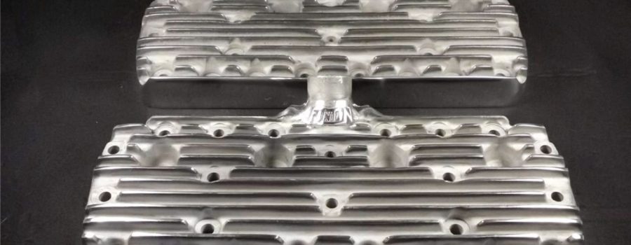
I’ve run both Offy and Edelbrocks on my present 286″ engine. I prefer the Edelbrocks. There isn’t a left and right head on the Offy’s I’ve run…. they’re both the same. But Edelbrocks are different. One head has more cc than the other. This helps compensate for the offset of the valves on a FH. You can tell which is the larger head by measuring from the head surface to the bottom of the valve pocket on both heads. The one with the bigger dimension is the larger head. The larger cc head goes on the passenger side of the engine. Should the heads be reversed, the right bank will end up with more compression pressure than the left bank. Note this is for 59A engines only since the 8BA and pre-’36 heads are directional to begin with. With a 3-3/8″ bore and a 4″ stroke, the compression was about 10.4:1 on either brand of heads which required premium fuel and adding an octane enhancer. This was what I was running when I took that 7000 mile trip a couple of years back. That’s a lot of additives at considerable expense.
Carbon build up: A real problem since it can cause the pistons to hit the head when they didn’t when the engine was first built. Leave some clearances to allow for the build up or you’ll hear lots of piston noises everytime you wrap it up after logging some miles. This goes for the valves too. Remember carbon build up increases compression pressure and leads to detonation.
Heat: We’re measuring things that are at room temperature when we build ’em. Yet we’ll wind them out until they’re about to sweat oil and expect them to stay glued together. Remember the rods stretch a lot under heat and rpm. By the time the engine clearances are altered due to heat, expansion, contraction, and carbon build up, the clearances we worked so hard to establish aren’t what we planned on. Set them up with plenty of clearances to keep things from hitting other things and decrease friction.
Recessing spark plugs: If you recess the plug seats 0.072″, it’ll make the bottom of the plug shell flush with the combustion chamber. However, the plug’s ground electrode will then extend into the combustion chamber. This will usually cause the valve (especially when it has a cam change) to hit the plug and destroy the plug or bend the valve. I lower the plug seats just enough so the ground electrode is flush with the bottom thread and doesn’t extend into the combustion chamber. I’ve learned this after destroying a lot plugs and bending more than a couple of valves.
Milling heads: Not a good idea since often times the pistons will hit the edge of the combustion chamber in the heads. Especially if you’re boring it big. I clay all pistons and valves. I use a set of used head gaskets and install the heads. After torquing them down, I turn the engine over two complete revolutions. Remove the heads and measure the clay thickness. This is the only way I’m comfortable verifying clearances.
Alterations to heads: I use a cutter on die grinder. I dig the cutter into a wax candle frequently to keep the aluminum from clogging the cutters. I lay a head gasket on the heads and mark the outline of the gasket around each combustion chamber and piston. This marks the area I’m going to grind on. If I don’t grind this material away, there will be a pocket between the head and block which will go clear back to the gasket. Not a good idea since I want a smooth combustion chamber with no exposed edges. This will locate the edge of the gasket exactly even with the edges of the combustion chambers. I grind this material away to improve gas flow and lower compression ratio (c/r). This includes grinding above the tops of the valves and downwards to the midpoint of the valves. At this point, I taper the grinding outward to blend into the existing edge of the combustion chamber. The “step” is to be modified next to improve flow and further lower the c/r. I want to relocate the top edge of the step towards the center of the dome. I measure 0.240″ from the top of the existing step and scribe a line. I begin at this line and grind the aluminum away. I grind a gently slope so the step becomes a gradual ramp. I’m done grinding. All that’s left is to polish the chamber and cc the heads. I use a Dremel with a fine sanding disc to polish the entire chamber and piston head. Then I cc the heads to verify they’re all within my plans. Time to do both heads is about 4 hours.
The original c/r was 10.4:1. It is now 9.5:1. This is about right for using premium fuel. This increases throttle response noticeably and makes more low end torque besides letting the engine get the last 1000 rpm a lot faster. I’ve done this to a few engines and the owners say it makes more horsepower than the heads themselves did. Please remember, this is what I do and is my opinion only…………… rumble seat
COMMENTS:
From: cobra Sent: 10/31/2002 10:22 PM
rumble seat:
Really interesting. Can I ask you a couple of questions. You have a 286″ engine. What type of piston do you run. What cam do you use. Are you running 1.6 valves?
Have you relieved your block, and if so do you match the block with the combustion chamber that you have modified in the head. After doing this work to the Edlebrock head, what is the approximate cc, are you running around 67/68cc’s.
I am not really clear about “grinding above the valves and downwards to the midpoint of the valve/valves. Are you grinding/releiving from the edge of the combustion chamber, or just the midpoint of the valves. How much do you take off above the valves, and do you do it for both intake and exhaust or just intake. Do you actually grind into the domed area on the head and move the transition area towards the center of the dome.
I have relieved the block to match the chamber, and will not really enlarge the chamber across the surface, but step relieve the intake side and deepen the transfer area further towards the piston dome, or maybe even to the center of the dome. What do you think. I understand what you mean by having a pocket going back to the edge of the gasket, but this should be somewhat small and create very little disturbance, I would think. Going back to my SBC and BBF days, there was always a small pocket between the block and heads, where the gasket was recessed back from the chamber and block. Less with steel shim gaskets, but still a gap. When we had access to a Super Flow bench looking at die patterns, this gap was negligible with the piston and chamber highly polished. You could not see any backwash at all. Of course these were higher RPM motors. Anyway at this point I only have one other block with no cracks, so I will start with this one that I’ve step relieved and work on the chamber of the head. One other comment. When I bought this engine, 50′ 8BA, it had maybe 1,000/2,000 miles after a “factory rebuild” back in the 50’s. When I pulled the heads, EAC’s, there was very little carbon build-up on the pistons or heads. You mentioned a lot of carbon build-up, why is this. OK, no more questions, I promise. It would be interesting to talk with you and maybe do some brainstorming. If you would like, you could give me your phone number XXXXXxx@hotmail.com and I would be glad to call you on my nickle if you give me a time.
I really appreciate your help.
From: fitts Sent: 10/31/2002 11:21 PM
rumbleseat – I have, but have not installed a set of “old”
Edelbrock heads (motor was already together before I got them,
and need longer studs on lower block to install). Glad for the
information, will keep this on file. Wish you’d write a book.
I’d stand in line to buy it.
From: Sopp Sent: 11/1/2002 12:30 AM
Hey Rumble,
My machinist was telling me today that it’s better to have
the gasket hole slightly larger than the bore so that the edge
of the gasket doesn’t get too hot and start burning away. I
noticed that a stock gasket for a 3-3/16 bore (at least the one
I have) has an exactly 3-3/8 diameter hole. He said these were
not a good idea with a 3-3/8 bore engine (the 3-3/16 bore gaskets
I have are just being used to hone engine to it’s final 3-3/8,
I’ll be using big bore gaskets for final assembly). Am I explaining
this understandably? This seems to contradict what you said
above. Your opinion please. Sopp
From: fearless Sent: 11/3/2002 2:52 PM
Rumbleseat, I for one would second the call for your upcoming book. I have planned to do some cleaning up on my Offy 400 heads this Winter and am very interested in your step relieving and just how that ends up looking, a picture tells me a lot since I am not a professionally trained machinist and was only going to unshroud my spark plugs and do a mild gasket match and polish. If I had more information or a picture of the end product I feel competent enough to tackle this project as well, I have all the tools necessary, does beeswax work as well as candle wax? Thanks, Dick
From: rumbleseat Sent: 11/3/2002 3:47 PM
Sopp, cobra, fitts: Sorry about not getting back to you sooner, but the site wouldn’t let me yesterday. Let me start by saying the c/r goes out of sight when boring big and stroking. Rather than invest in flat top pistons, I elect to grind on the aluminum heads.
Sopp: I don’t disagree with your machinist concerning exposing head gaskets in the combustion area. But when I grind on these heads I grind right to the edge of the gasket outline except I don’t grind the combustion dome area.
Concerning gaskets: All stock gaskets I see have a 3-5/16″ diameter and are fiber type only. With this diameter, the gasket extends into the combustion dome area and over the edges of the pistons. Maybe it’s just the brand of stock gaskets I’ve been using (Fel-Pro). So I use big bore copper gaskets when boring bigger than 3-5/16″. They only come in copper and are about $35 each. The copper gaskets are 0.050″ thick after torquing.
fitts: Suggest you check Bill B’s techno site for stud information. They can be tricky. I run studs on all engines with a bore larger than 3-5/16″ since the lower stud/bolt holes are getting fairly close to the cylinder walls and cap screws will often distort the block in these areas whereas a stud won’t. Just my thoughts.
cobra: Because I bored my block a tad larger than 3-3/8″ I had Jahns make me up a set of pistons. Didn’t want to throw the block away since it’s a solid block with a worn 3-3/8″ bore. They are Jahn’s 3 ring semi-dome, solid skirt racing pistons. But there are several excellent other brands on the market. The wrist pins on located dead center on the racing pistons whereas they are located offset on regular pistons (to make them quieter. But the racing pistons seen to produce a tad more hp than stock pistons. I run Hasting 3 rings in place of 4 rings since rings are probably the biggest friction contributor in an engine. And friction builds heat and reduces hp. Valves: I’m running 1.6 Chevy intakes and 1.5 Ford exhaust. Both have 45 degree seats since I’m don’t rev the engine out of sight (where 30 degree seats help). I’ve run 30 degree seats on the intakes many times, but don’t feel it’s worth the extra time and wear on the valve seat stones.
Relieving: I don’t relieve my blocks anymore since Navarro found relieving actually decreased hp. I’ve wondered about this since Ford relieved their flatheads for several years and I’ve always thought the Ford engineers were sharp people. The relieving you’ve done sounds good. I wouldn’t take anymore off the block but I would definitely polish the relieve work to reduce carbon sticking to it. Stock reliefs lower the compression ratio 0.5 points in case you’re interested.
Carbon build-up: The gas (?) we’re getting today doesn’t form hard carbon like the old gas did. Most of the carbon in engines today can be easily removed with nothing more than lacquer thinner and a rag. This eliminates possible damage to the aluminum heads with wire wheels, and carbon scrapers. But carbon still builds and shouldn’t be forgotten in our plans.
Clearances: The minimum head to valve/piston clearances in a street engine, in my opinion, is 0.050″. Anything less than this always seems to cause some type of problem down the road. Again, just my opinion.
Grinding: Sorry I didn’t make my grinding description clearer. Let me try again. I want to remove the head metal that extends into the gasket area. Which is why I outline the gasket on the heads. Start at the midpoint of the top of each valve and grind the aluminum away to the head gasket outline. Grind the sides down to the step of the combustion area. Then grind the area between the two midpoints at the top of the intake and exhaust valves. This is usually 0.040″. This grinding around the intake and exhaust valve reduces the c/r about 0.6 of a point. The chamber will now be even with the gasket outline. The width of material removed AT the step on the intake valve side was 0.120″. On the exhaust side, the material removed AT the step was 0.065″. The step was then ground. I scribe a line across the combustion squish area 0.200″ from the edge of the step where the squish dome starts. Grind the material away to make the step disappear by blending it to eliminate the radical step and make it a ramp towards the center of the pistons. After polishing the heads are cc’d. The right head has 66.0cc and the left head has 63.0cc. Understand these are 59 heads and not 8BA. I’ve never done 8BA heads, but I think grinding will help them too. Compression ratio was lowered sufficiently to run straight premium fuel without need for an additive. For Edelbrock heads, the distance depth between the head’s finished surface and fly cut for the intake valve is right at 0.030″ more for the right head than the left if you’re interested.
rumble seat
Was this article a help? Consider supporting the Flat-Spot by becoming a Premium Member. Members get discounts with well known retailers, a cool membership packet full of goodies and your membership goes toward helping us upkeep and expand on this great archive.


