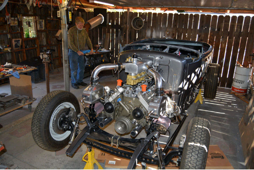
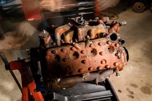
Get ready for one of the coolest methods to hide fuel injection on your Flathead ford. through the genius of Allan Wylie and Vergil Dawson, we’re excited to show you the step by step method of how this process was done and how one of the most wild Flathead Fords we have seen in some time was created. Honestly look at this amazing beast.
Written By Vergil Dawson
I was trying to figure out how to hide the fuel injection when I built my 8ba. Allan Wylie from NZ seen what I was doing and offered to send some pictures of how he done his and I said sure, so I can blame him for my setup or thank him for being so generous.
This will be in Three parts,
– Part one is the engine build with the hidden fuel injection.
– Part two will go over how we set up the intake
– Part three is the dual Turbos.
This engine went into my ‘30 Ford roadster. There are pictures from my ’30 Ford pickup with an 8ba with the same fuel injection as the 8ba in the roadster, I combined pictures from both builds because one showed what was happening better than the other one. There is probably much better ways to do the hidden fuel injection but this is the way I done mine and still had the looks of the Flathead with four two’s.I was trying to figure out how to hide the fuel injection when I built my 8ba. Allan Wylie from NZ seen what I was doing and offered to send some pictures of how he done his and I said sure, so I can blame him for my setup or thank him for being so generous. This will be in two parts, Part 1 is the engine build with the hidden fuel injection and Part 2 is the dual Turbos. This engine went into my ‘30 Ford roadster. There are pictures from my ’30 Ford pickup with an 8ba with the same fuel injection as the 8ba in the roadster, I combined pictures from both builds because one showed what was happening better than the other one. There is probably much better ways to do the hidden fuel injection but this is the way I done mine and still had the looks of the Flathead with four two’s.
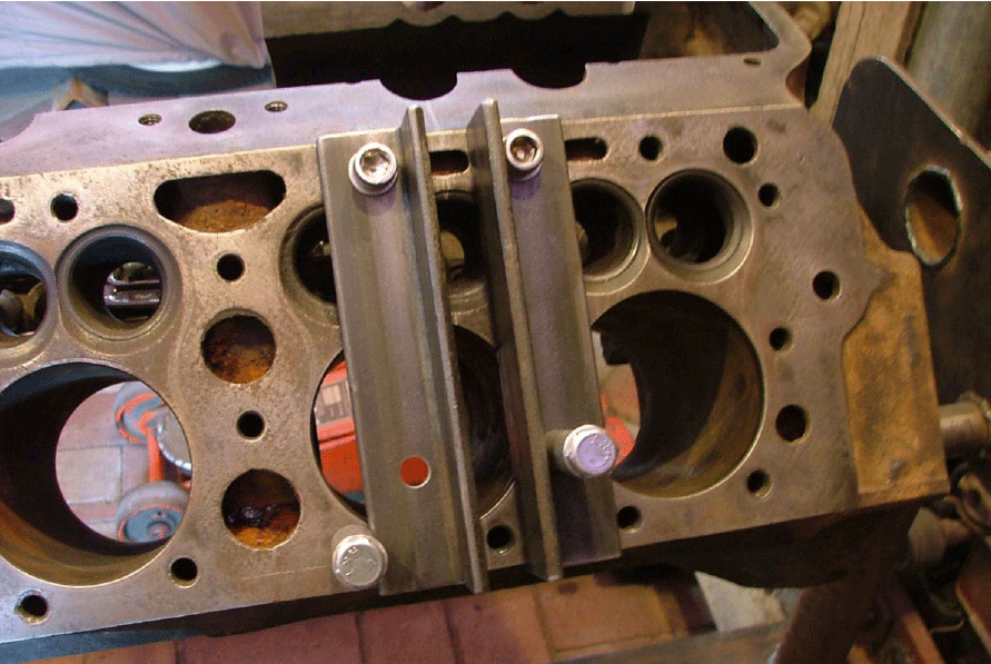
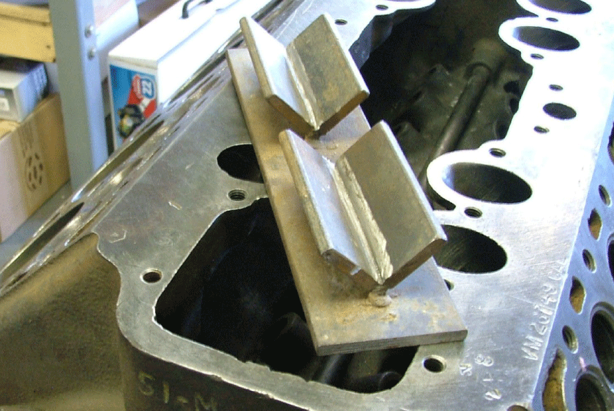
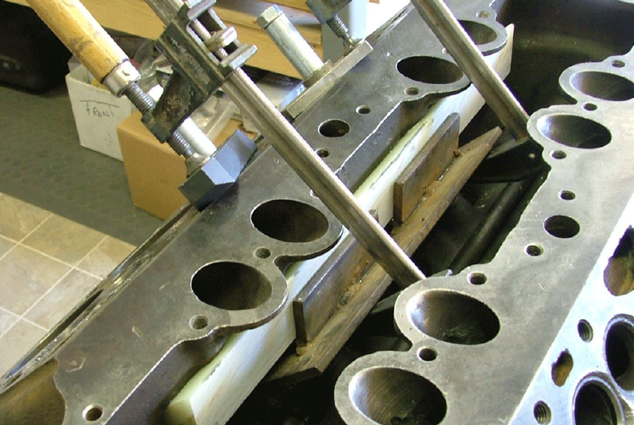
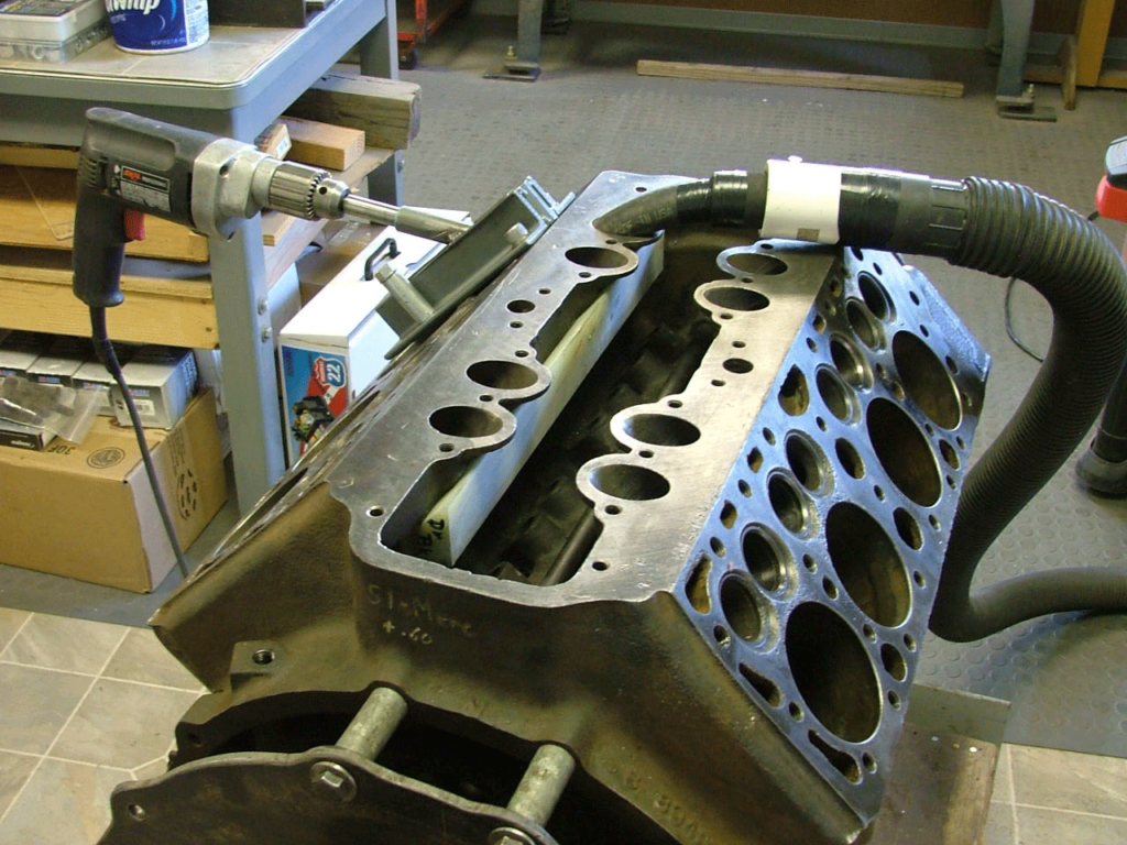
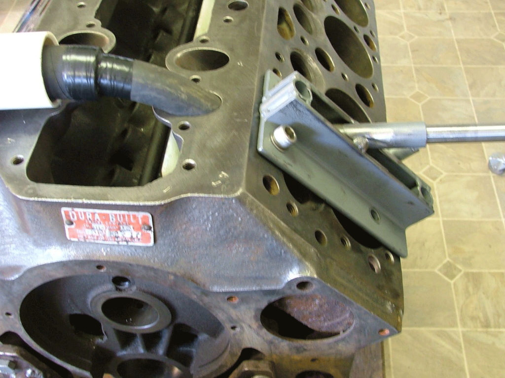
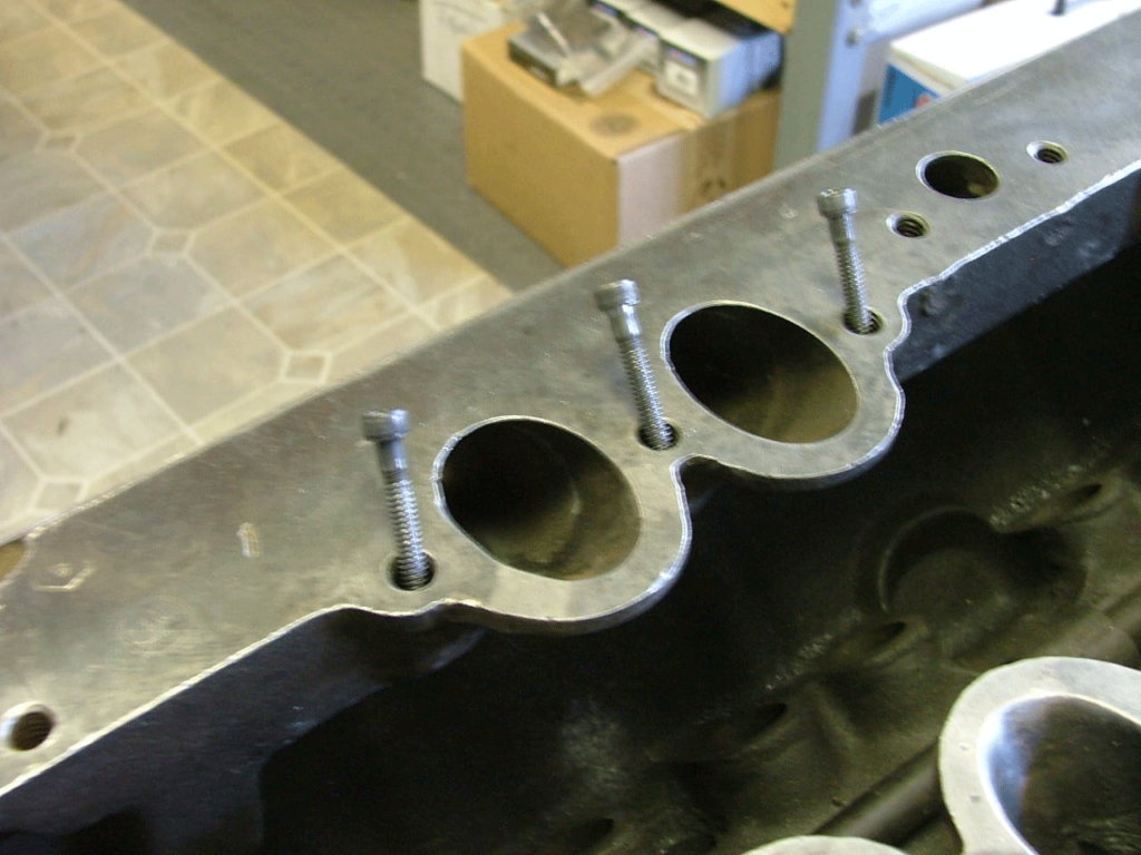
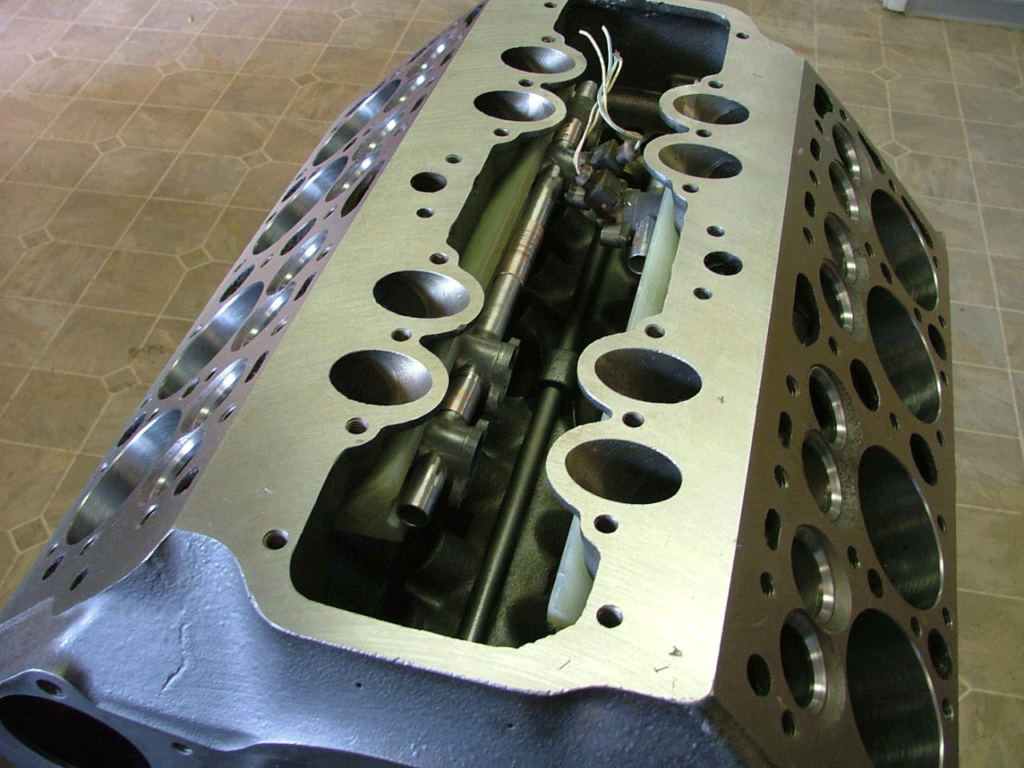
This is the starting of the jig to drill the holes for the fuel injection, The pictures will show between the angle irons tubing spacers was welded in place as well as the boring guide. I never measured the angle of the guide but it is up very close to the valve seat and if the valve chamber end is to high there will not be enough room for the injectors.
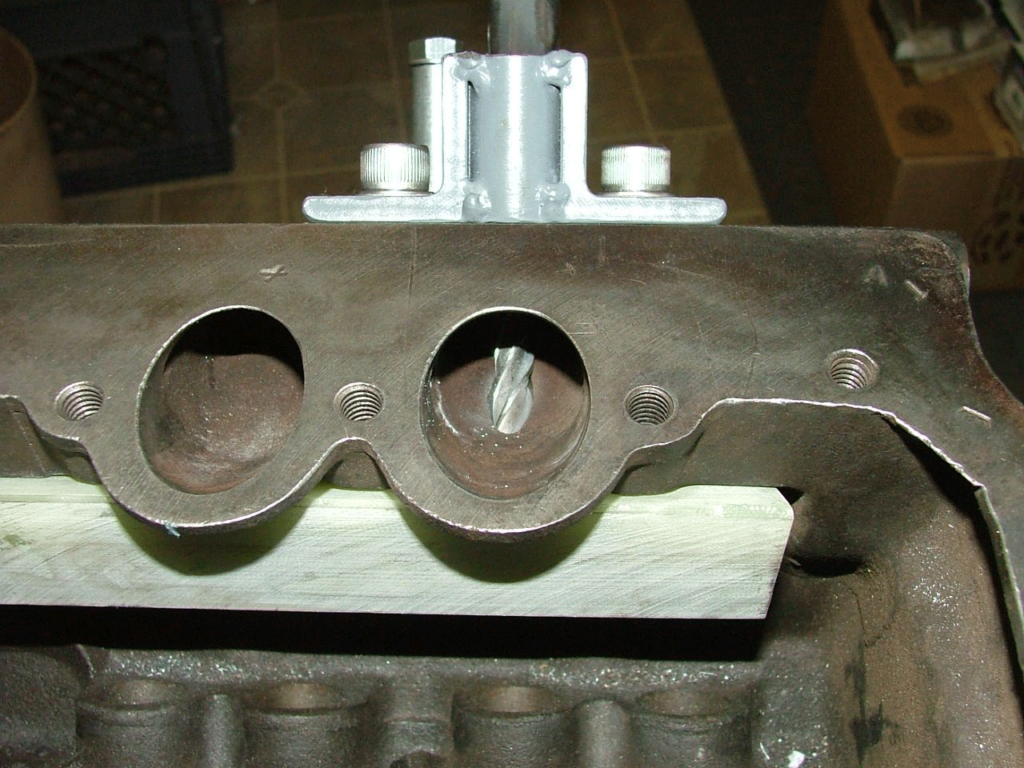
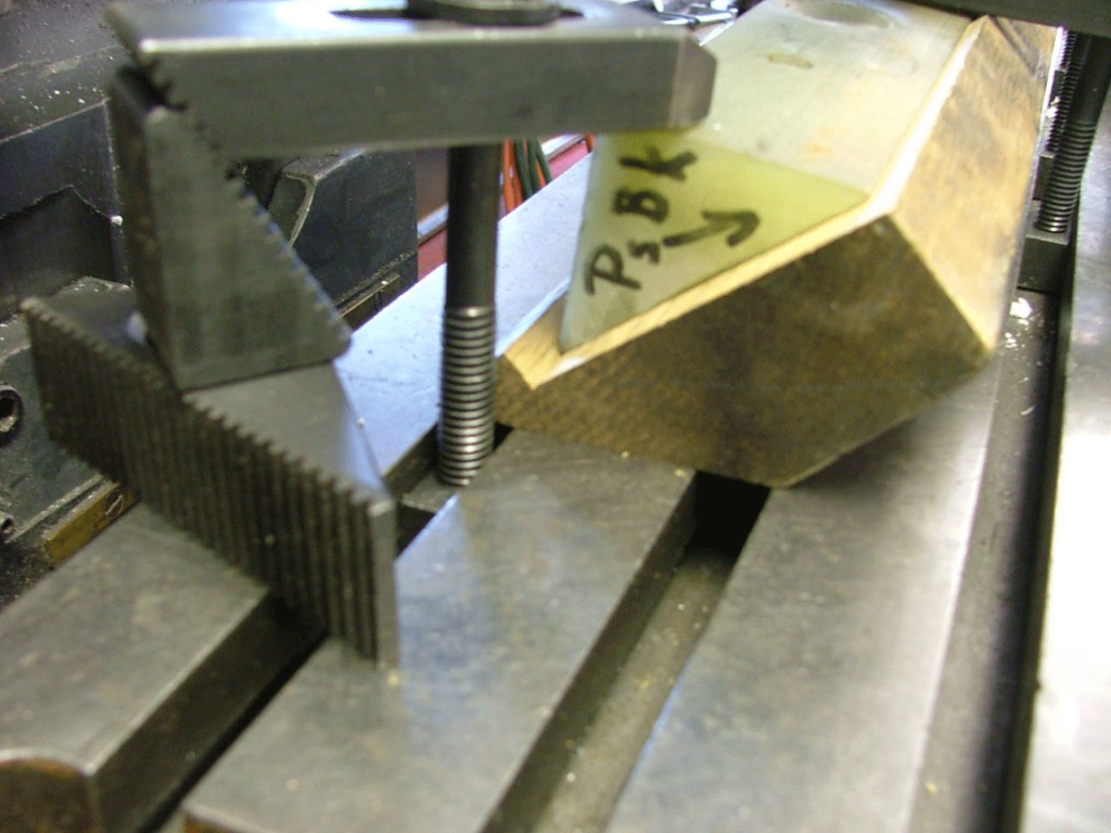
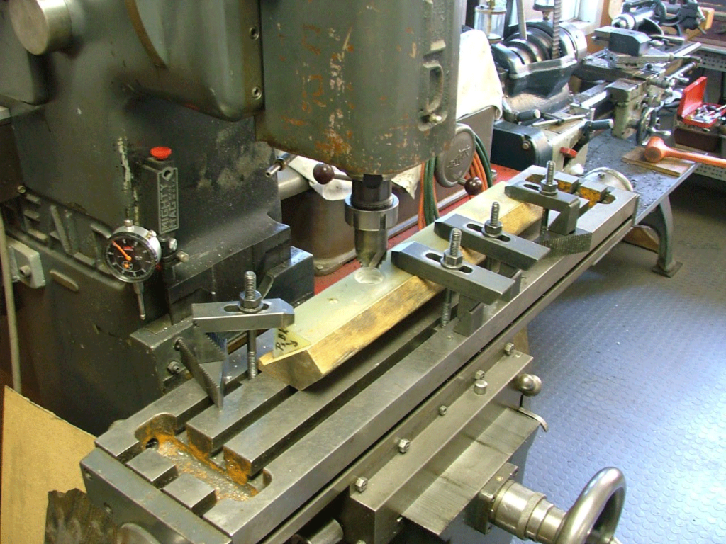
This is a fixture I used to hold the Phenolic block in place along with clamps while drilling.
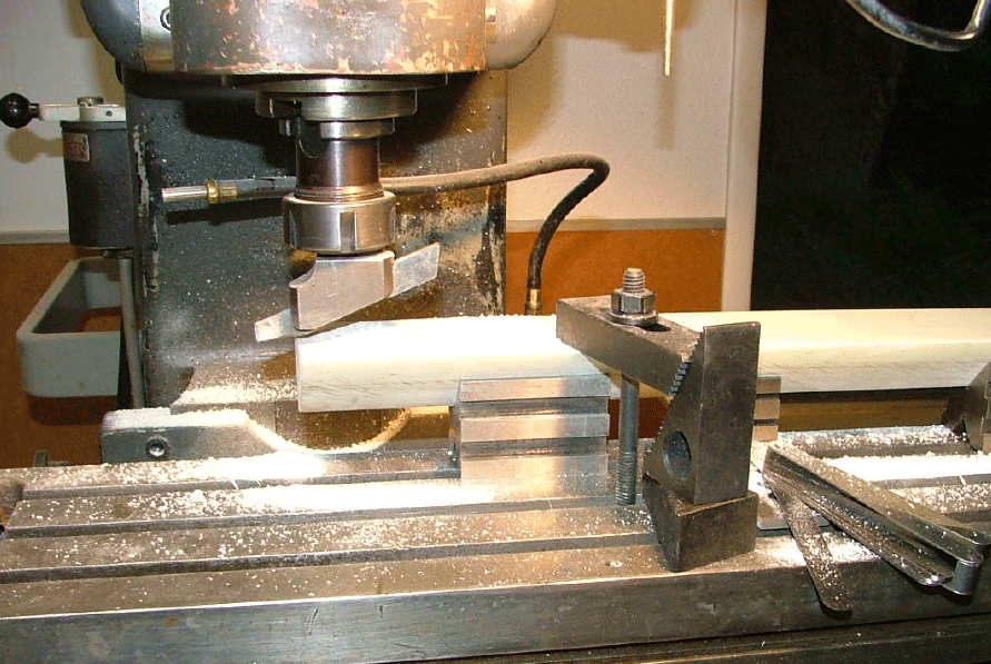
The Phenolic block being trued up after it was cut corner to corner from a 2” square piece of stock.
The Phenolic block in place ready to drill mounting holes and fuel injector holes.
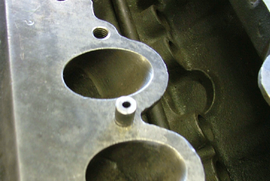
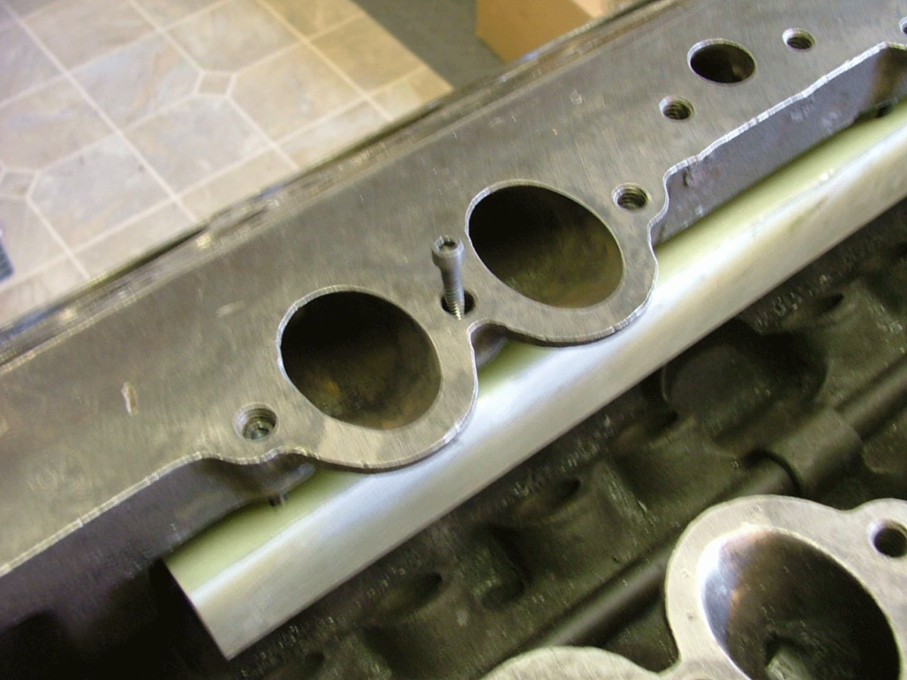
A drill guide to make sure the holes are centered in the holes for allen screws The drill size will be for tapping for 10-24 threads. After the holes are all the way through the Phonelic block and the block is removed the holes in the engine block can be enlarged for the screws to drop through up to the bottom of the head.
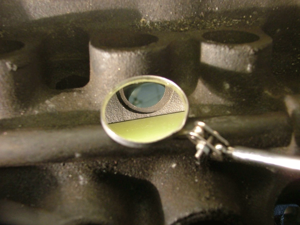
Make sure the Phenolic block does not cover the valve guide horse shoe retainer recess before any drilling.
Drilling holes all the way through the Phenolic block for tapping the Phonelic block for 10-24 x 1 ¾” socket head cap screws.
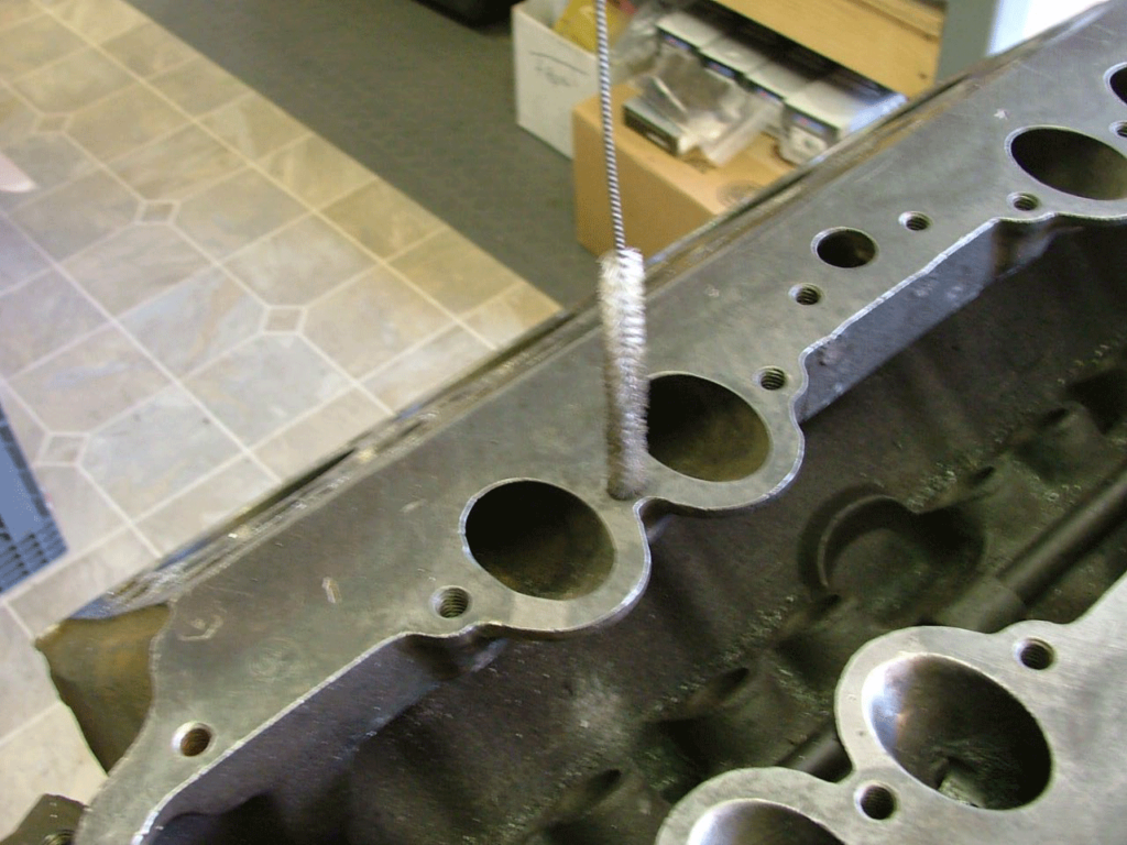
A brush to clean the holes out.
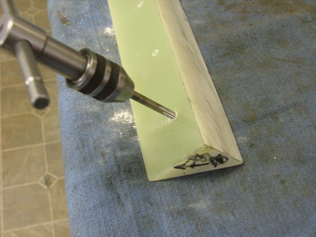
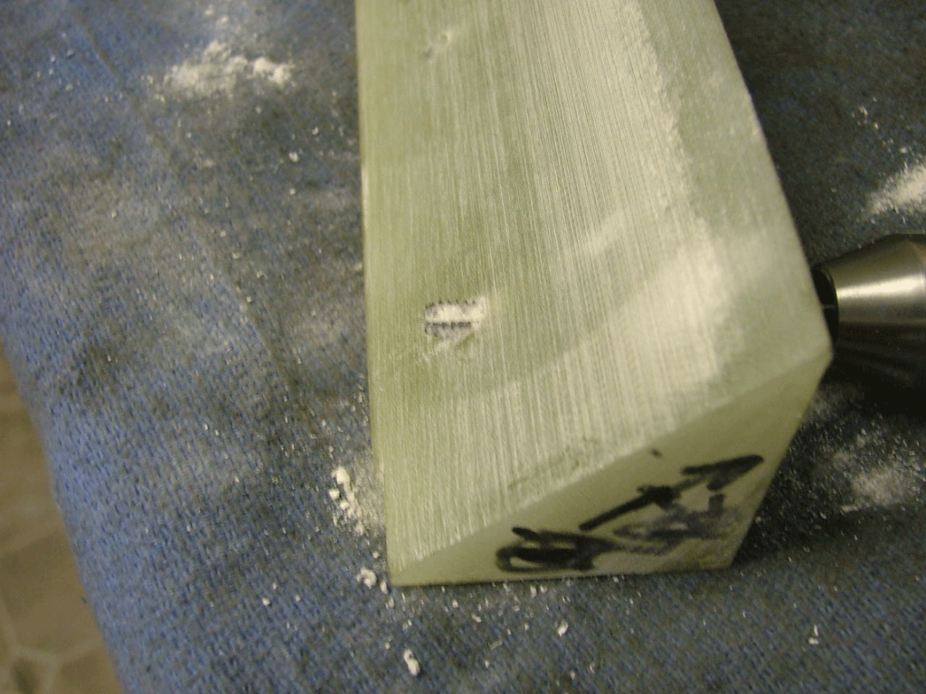
Tapping the holes for 10-24 screws.

Be sure the holes are tapped all the way through, don’t want the screws to bottom out before the block is tight.
Showing the screws that hold the phonelic block in place.
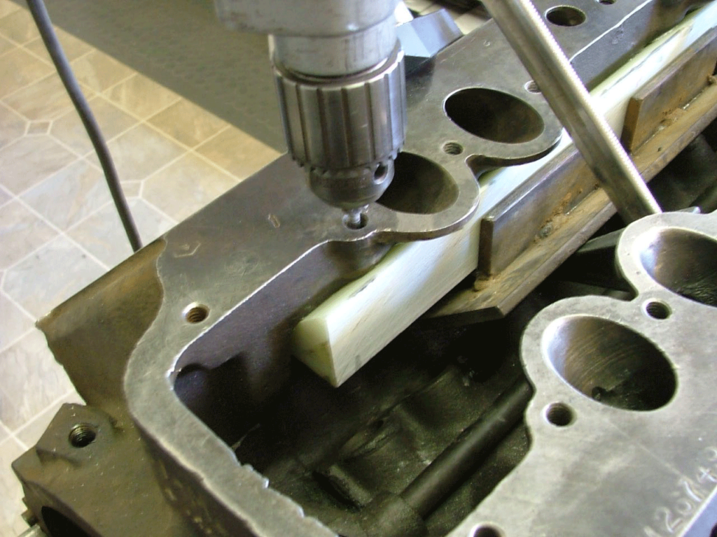
Using a shop vac to get rid of the metal as the fuel injector holes are drilled.
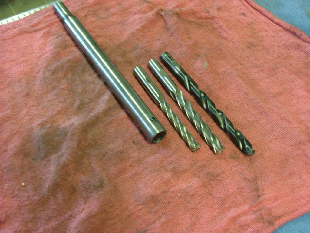
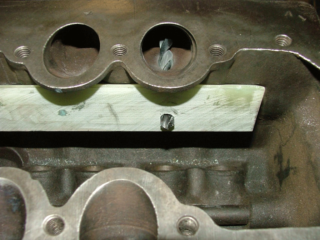
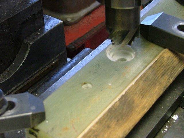
This is what I used, first is the small end mill to get the hole through the engine block then the larger end mill and finally the drill bit to finish through the Phonelic block.
Starting the first injector hole.
A note, be sure the mounting holes are laid out as perfect as you can get them. The jig will fit all the intake valve pockets using three bolts.
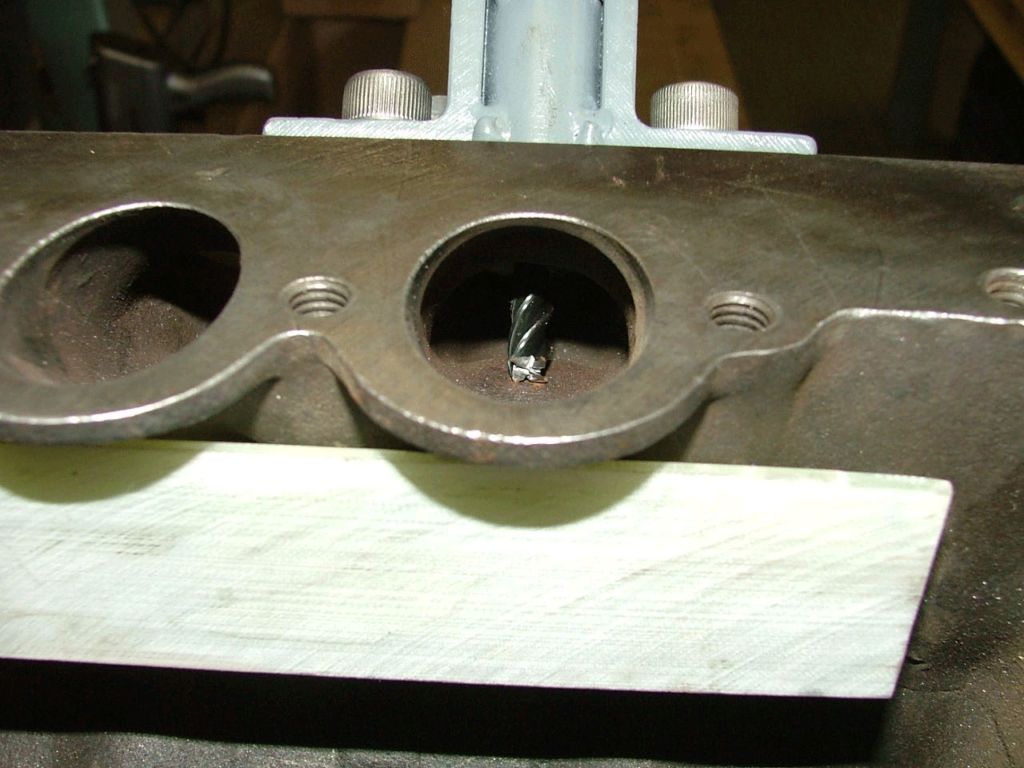
Using the larger end mill.
Using the drill bit to to finish the injector hole.
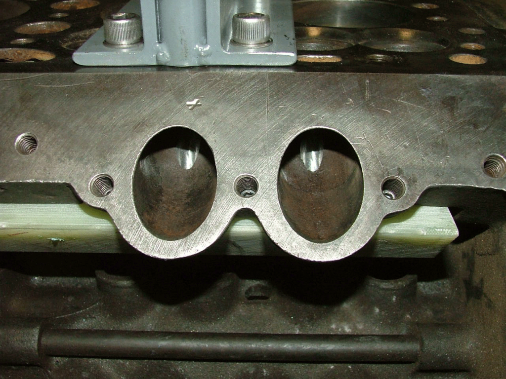
Finished holes.
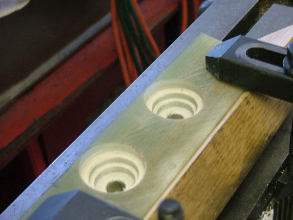
I made a hard wood jig to hold the Phonelic blocks to finish them.
It doesn’t show very well but I took the outside dimensions from the fuel rail and made a cutter that machines the hole in one step. It has been hardened, the Phonelic is hard on the tool bits.
I didn’t get a picture but there is a relief cut from one pocket to the next and out to each end of the block.
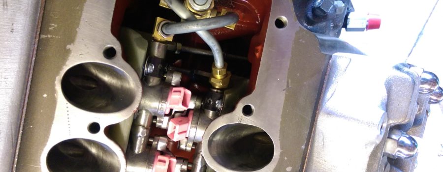
Cutting up the fuel rails from a early ’80’s Nissan Maxima V6. Here you can see the relief in the Phenolic block. The relief is for the welds or what ever you connect the fuel rails back together with. The one on the left needs welding, brazing or silver soldering and the one on the right is just started. It gets cramped in there by the time every thing is in place.
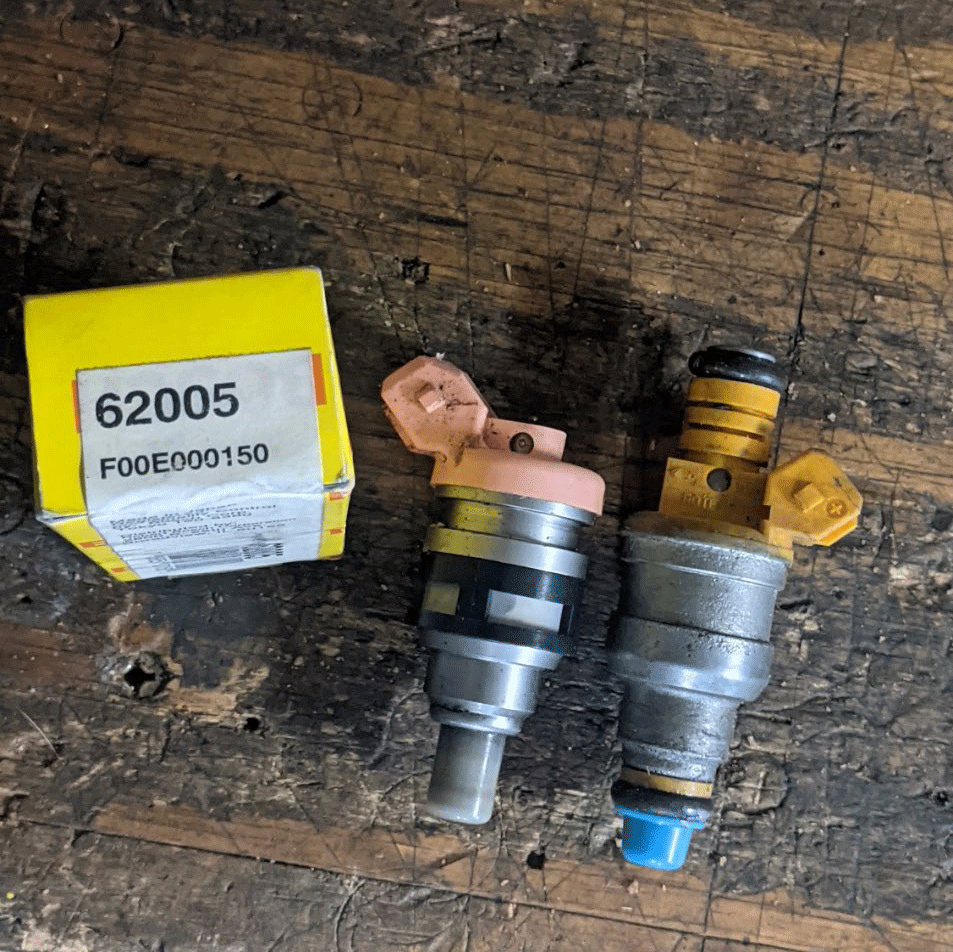
Used the Bosch 62002 Injectors because they are side load instead of end load like the injector on the right. Side load takes up less space.
Was this article a help? Consider supporting the Flat-Spot by becoming a Premium Member. Members get discounts with well known retailers, a cool membership packet full of goodies and your membership goes toward helping us upkeep and expand on this great archive.

