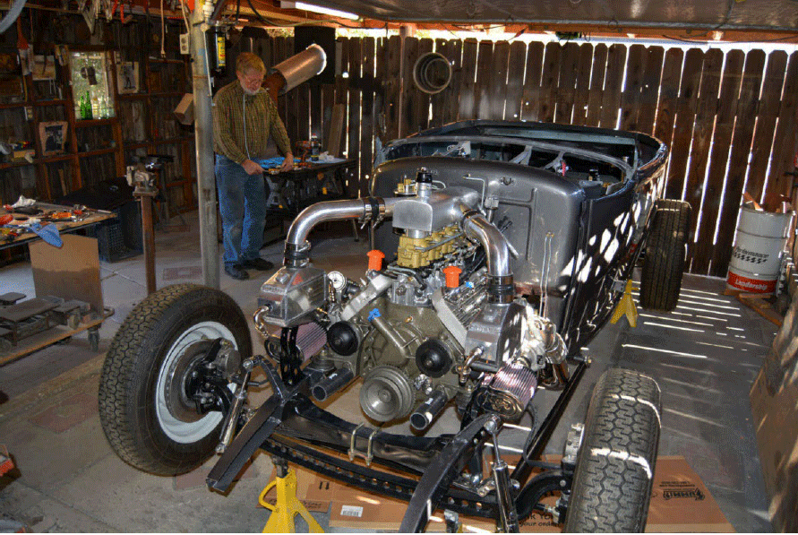
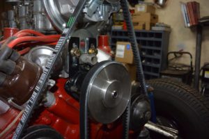
RECAP: Get ready for one of the coolest methods to hide fuel injection on your Flathead ford. through the genius of Allan Wylie and Vergil Dawson, we’re excited to show you the step by step method of how this process was done and how one of the most wild Flathead Fords we have seen in some time was created. Honestly look at this amazing beast.
Written By Vergil Dawson
I was trying to figure out how to hide the fuel injection when I built my 8ba. Allan Wylie from NZ seen what I was doing and offered to send some pictures of how he done his and I said sure, so I can blame him for my setup or thank him for being so generous.
This will be in Three parts,
– Part one is the engine build with the hidden fuel injection.
– Part two will go over how we set up the intake
– Part three is the dual Turbos.
This engine went into my ‘30 Ford roadster. There are pictures from my ’30 Ford pickup with an 8ba with the same fuel injection as the 8ba in the roadster, I combined pictures from both builds because one showed what was happening better than the other one. There is probably much better ways to do the hidden fuel injection but this is the way I done mine and still had the looks of the Flathead with four two’s.I was trying to figure out how to hide the fuel injection when I built my 8ba. Allan Wylie from NZ seen what I was doing and offered to send some pictures of how he done his and I said sure, so I can blame him for my setup or thank him for being so generous. This will be in two parts, Part 1 is the engine build with the hidden fuel injection and Part 2 is the dual Turbos. This engine went into my ‘30 Ford roadster. There are pictures from my ’30 Ford pickup with an 8ba with the same fuel injection as the 8ba in the roadster, I combined pictures from both builds because one showed what was happening better than the other one. There is probably much better ways to do the hidden fuel injection but this is the way I done mine and still had the looks of the Flathead with four two’s.
CONTINUED:
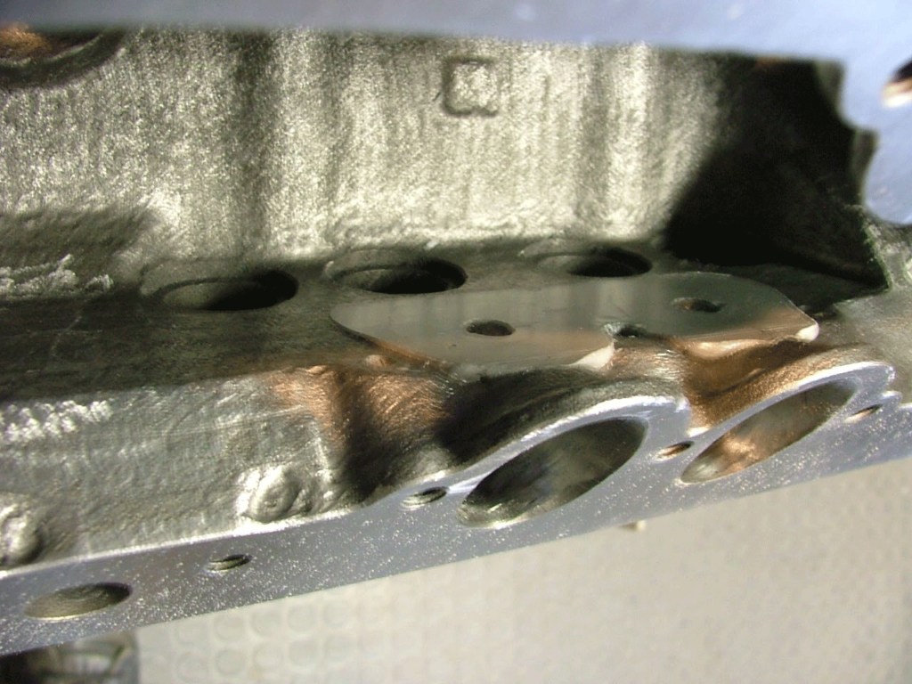
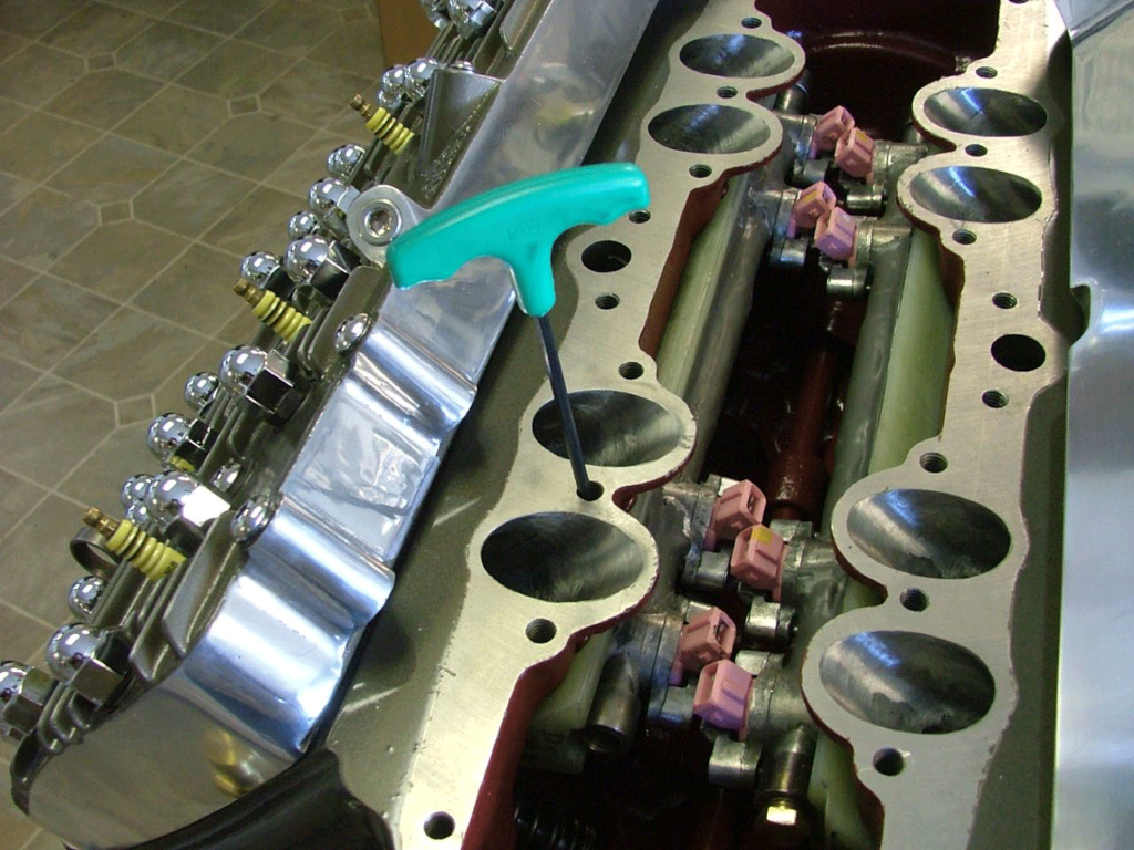
By now it should be looking something like this but it’s too rough to seal.
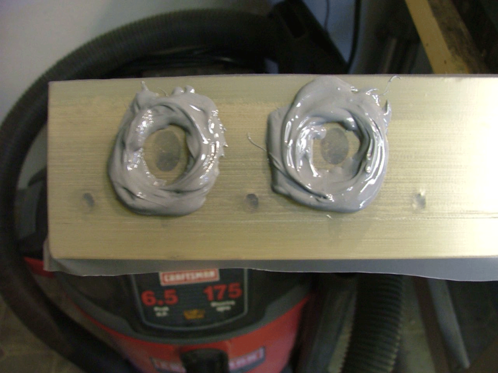
I used release tape on the Phonelic block and on the first injection project I used some aircraft stuff but the last one I used one of JB Welds products. This should give a nice smooth surface to seal against.
This is nice and smooth now. The holes in the block have to be cleaned out and make sure it isn’t in the valve guide horse shoe recess.
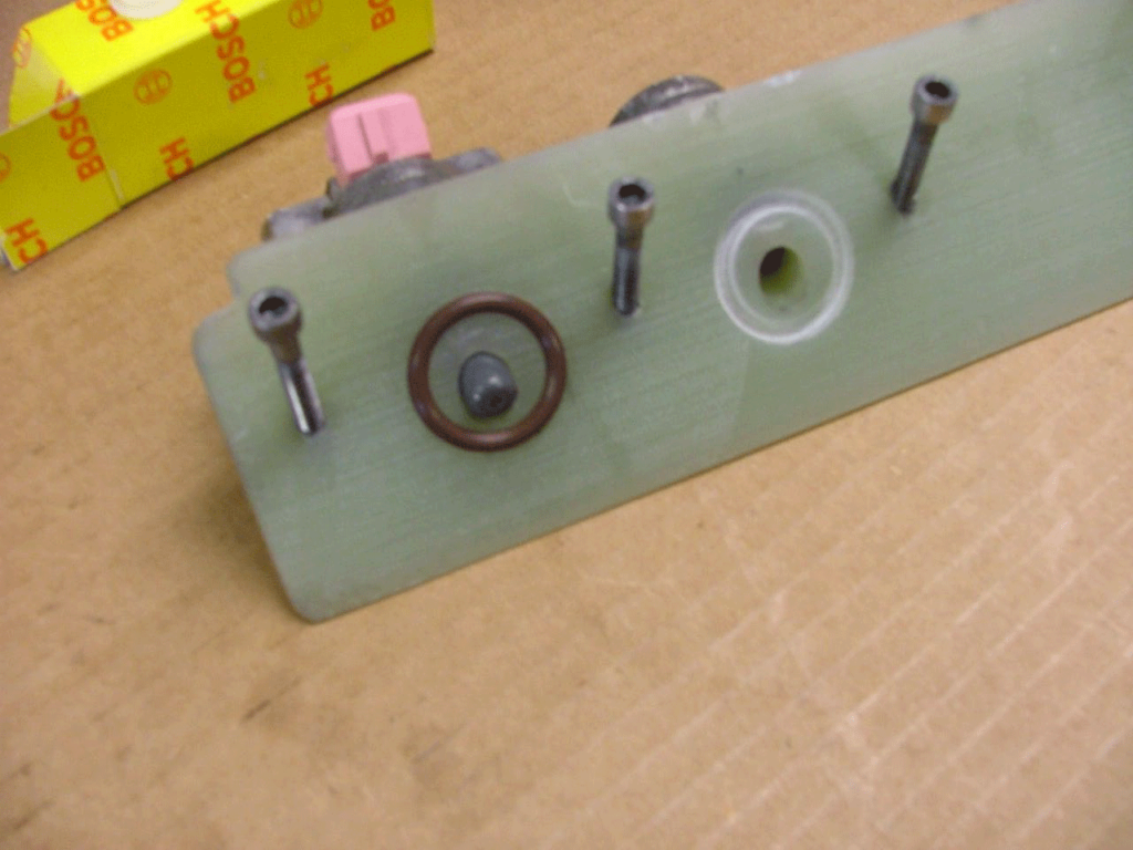
The o-ring seats was made from a diamond encrusted hole saw.
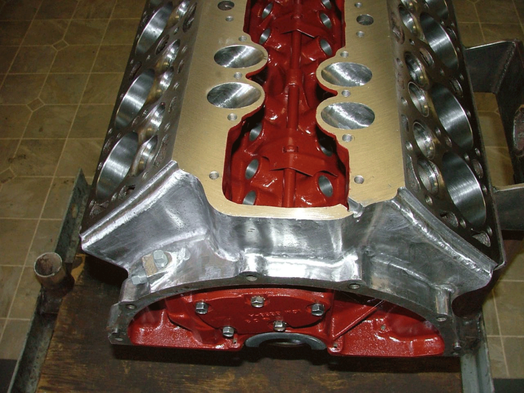
Was time to paint the block.
O-rings in place and now to button up the Phonelic block.
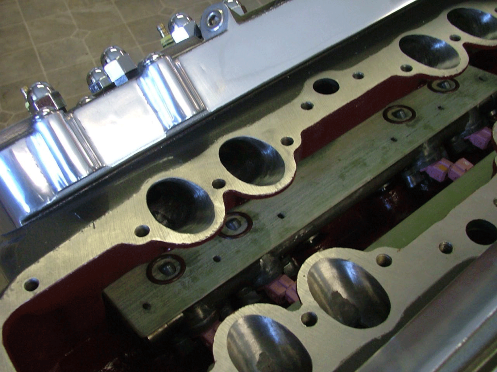
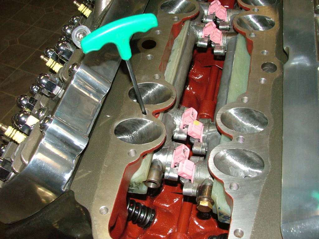
You have to put one before the other but both have to be in the valve chamber before tightening them up. This is not the final buttoning up, the blocks will be in and out a few more times. Before tightening up the Pholenic blocks for the last time, make sure the valves are all in and adjusted, check the adjustment again to be sure.
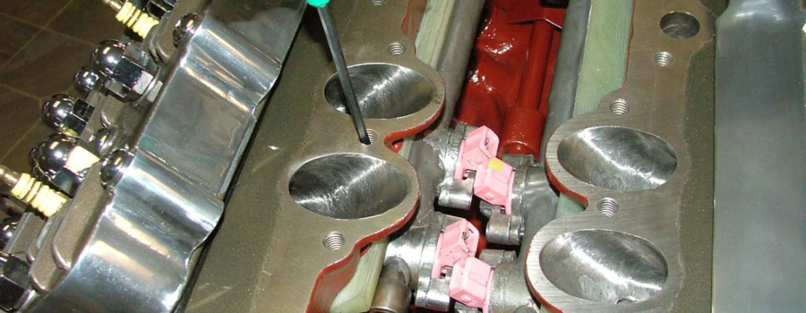
See how cramped it is and as you can see the injectors will need to be turned for the injector wire terminals to fit. The retainers that hold the injectors in place also need to have the ends rounded some. This picture also shows the threaded ends of the fuel rails and the relief for the fuel rails to fit into.
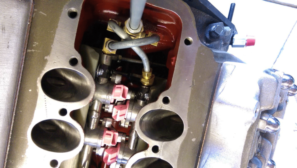
The fuel comes in at the back of the engine where the old fuel pump fits. The vertical tube is for the fuel inlet. There is a plug that drops into the old fuel pump rod bushing. Notice the clamps that hold the fuel rails to the Phonelic block. It’s crowded but it gets a little worse. When mounting the fuel rails to the Phonelic block be sure to use a high temp oil resistant RTV to seal it so the intake port vacuum won’t pull oil from the valve chamber to the intake valves. When wiring the injectors use wire insulation for harsh environments.
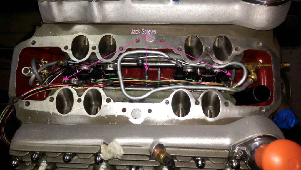
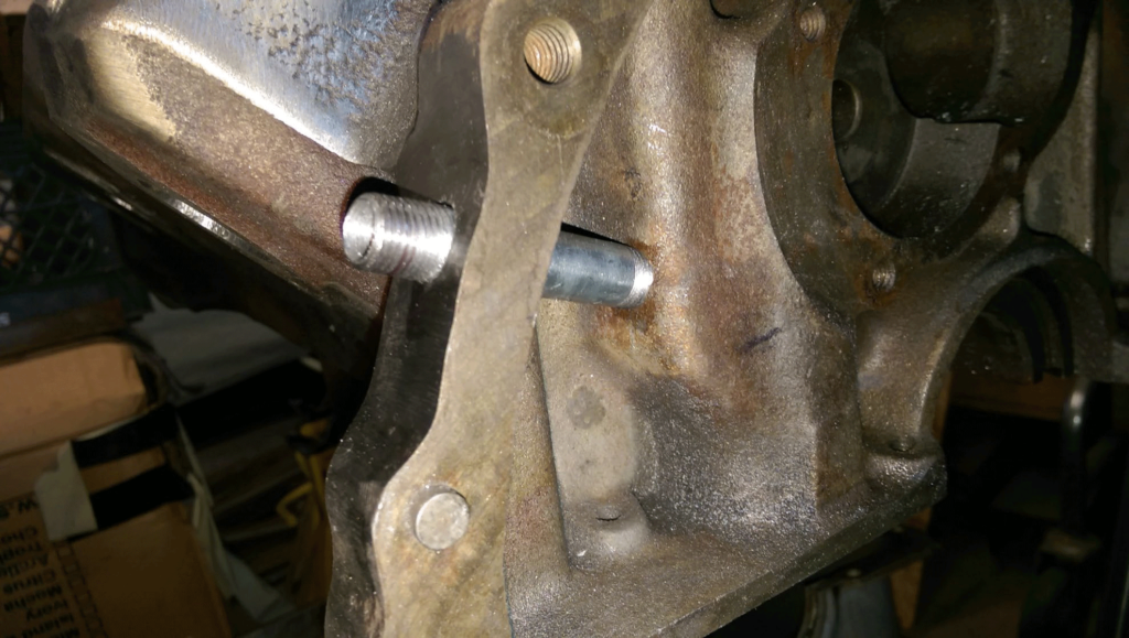
It’s hard to see and I didn’t get any pictures of the jack screws. I think this is them, sorry. The jack screws hold the bottom of the Phonelic block against the engine for a good seal and not have to wonder if it was sealing later. The blocks have a deep dimple to hold the jack screws in place.
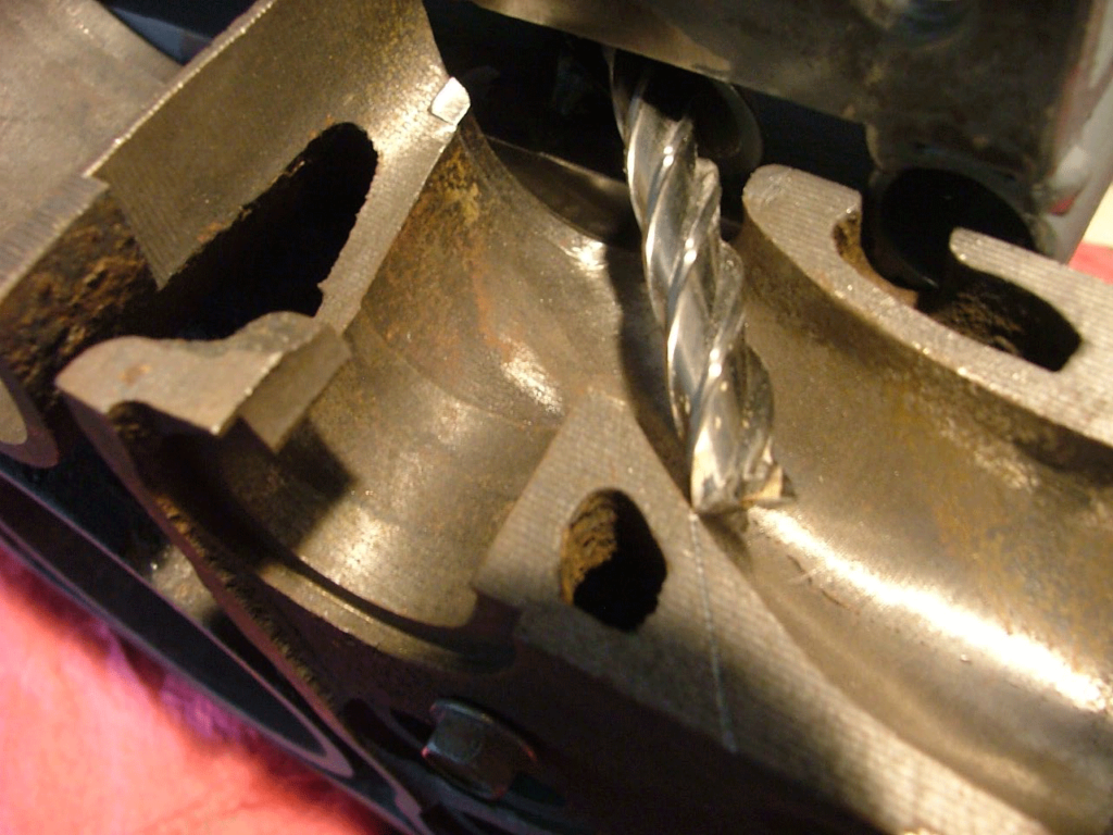
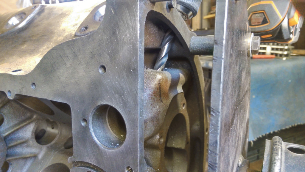
I had cut up a junk 8ba engine to see what was happening and decided to see what the injector angle looked like. Wow there is water and I didn’t know about it but didn’t hit any water out of the 16 injector holes on the two engines.

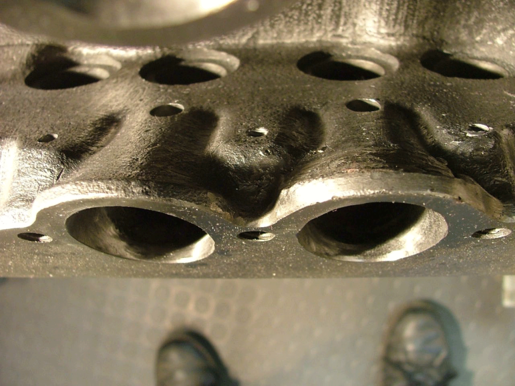
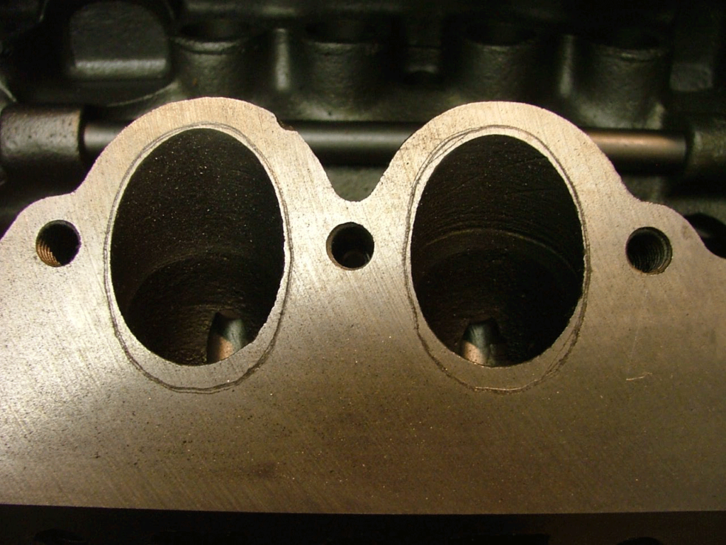
This is how much I had to open up the ports to match the 4×2 intake manifold runners.
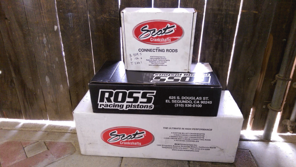
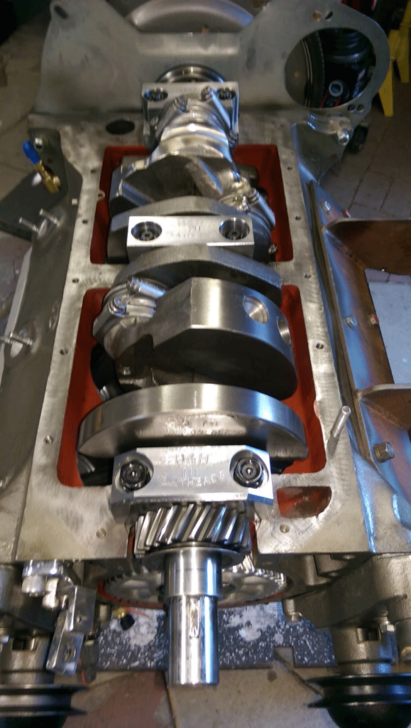
Using a Scat 4” stroke crankshaft, Scat H beam connecting rods, Ross pistons, Manley SS valves, hard valve seats, Schneider cam and valve springs, adjustable lifters, Melling 15 oil pump and H&H billet main caps.
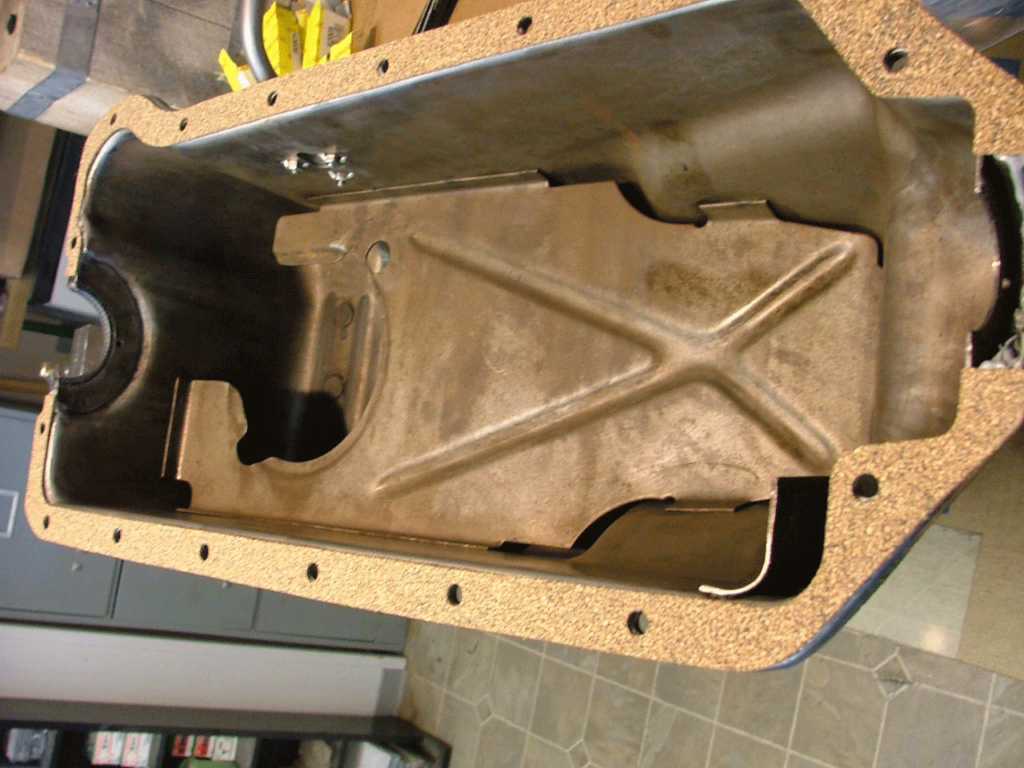
Using a late Mercury baffled oil pan with matching oil pump pickup screen that has a plate that finishes out the baffle
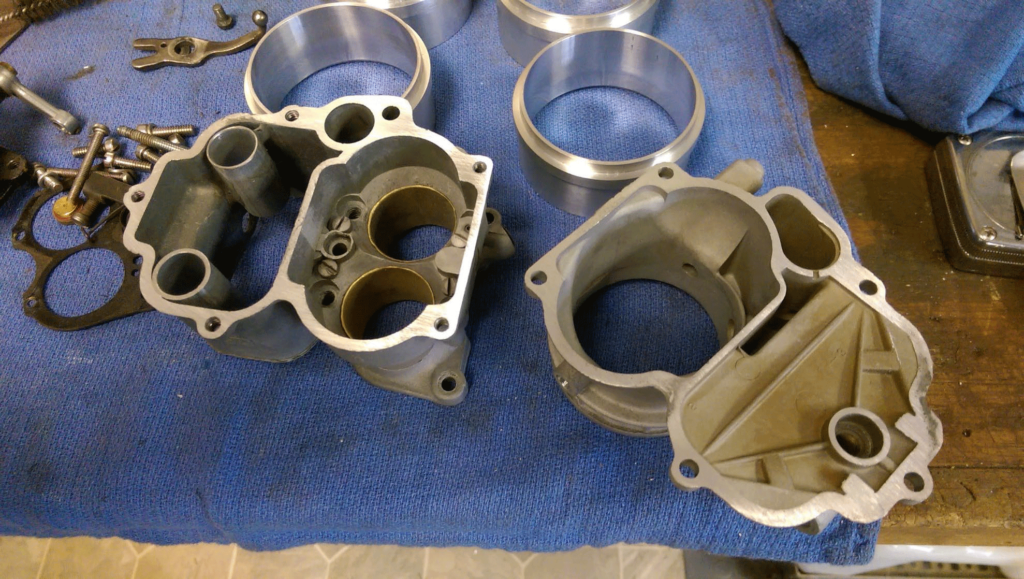
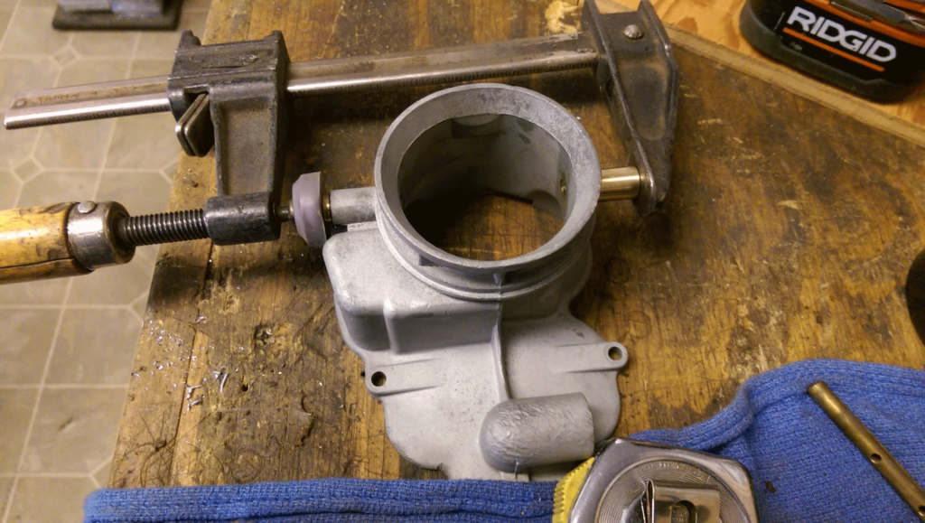
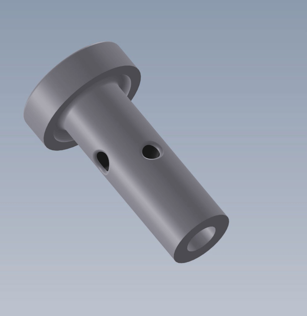
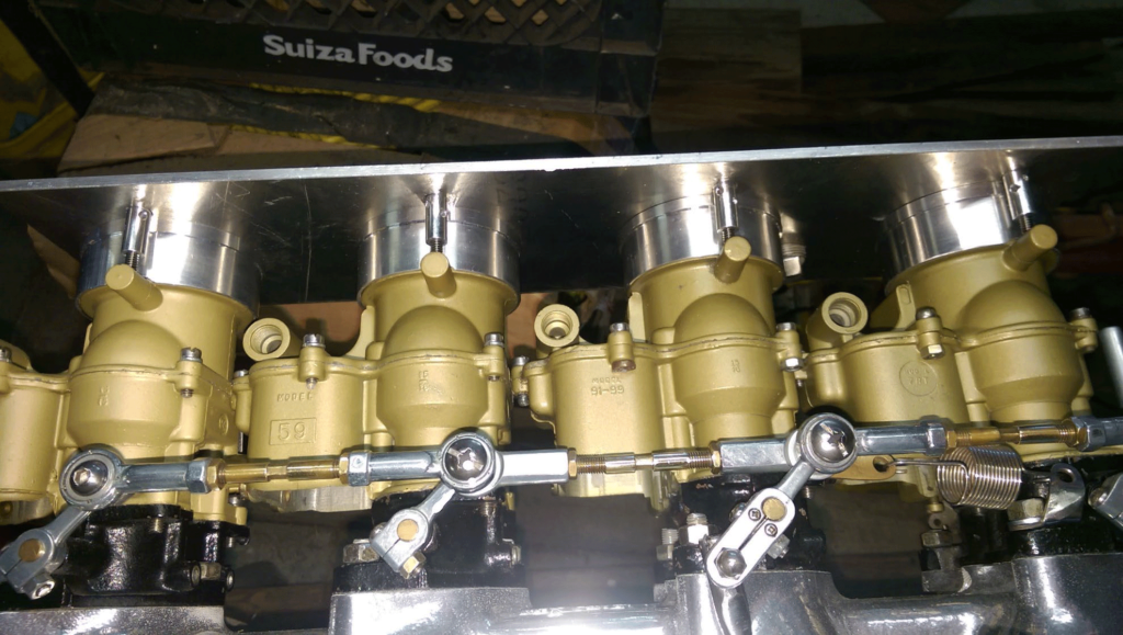
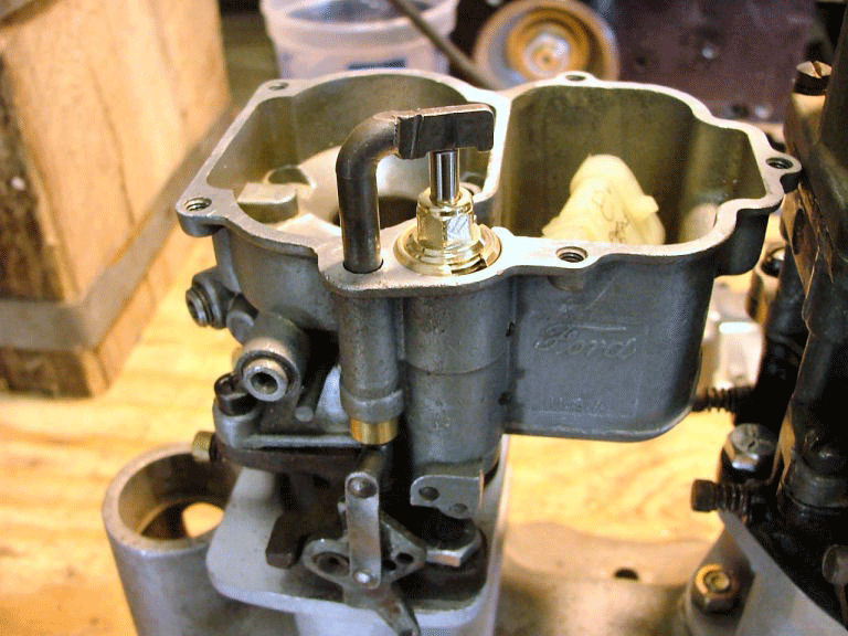
With fuel injection I am only using the throttle plates. The venturi was bored out and tubing pressed in for a smoother air flow and less restriction.
The choke plates and shaft were removed and round stock plugging the holes for the inlet plenum to mount to.
Drilled and tapped for screw studs to screw into.
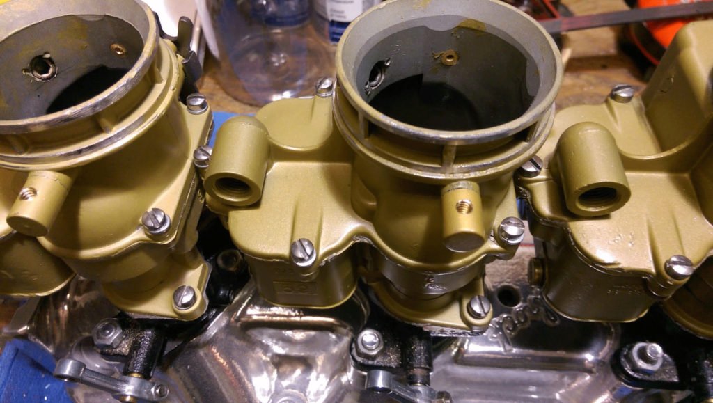
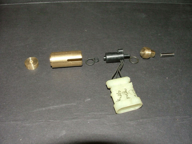
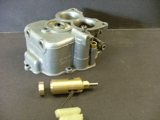
These are the hold down nuts for the plenum. The center hole is threaded and screwed down on the screw studs on the carburetors. Under the top flange is a recess for o-rings to fit for sealing. The small holes in the barrel is used for a small drift pin to screw it down tight to the carburetor, then a safety clip is inserted into them to keep them from loosening up and going into the engine.
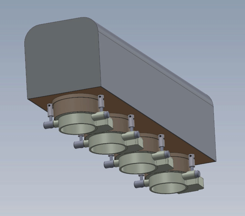
This is the plenum mounted showing the hold down nuts. Every thing is o-ringed to prevent air leakage. There is a sensor mounted in the floor of the plenum to measure air temperature going into the engine for the ECU input.
The carburetor fuel inlets has dummy lines run to them for looks (not shown).
The TPS (throttle positioner sensor) is mounted in the old accelerator location using the same linkage. It is a sensor from an ’85 Buick with fuel injection.
The adapter made to use the TPS sensor.
This shows the screw in the bottom of the housing for adjusting the height of the sensor for the correct voltage and shows the two small set screw holes to lock the sensor in place once it’s adjusted.
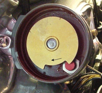
The distributor was gutted and a sensor mounted that lets the ECU know when #1 piston is coming up to TDC for full sequential fuel injection.
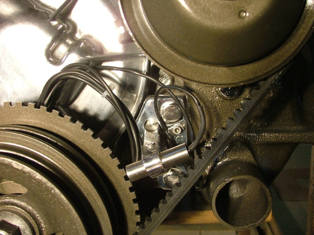
Crankshaft mounted toothed wheel for the sensor to send signal back for the ECU for timing and coil packs.
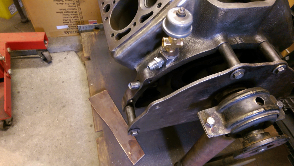
The oiling was modified to increase the oil flow and mounts the pressure outlet in a better position for the oil line going to the dual oil filters.
The bottom pipe is the oil pressure the next one up is the oil return to the engine. The original oil passage has been blocked off under the return fitting which now routes the oil to the oil filters. The two outlets on the brass tee are for oil going to the turbos.
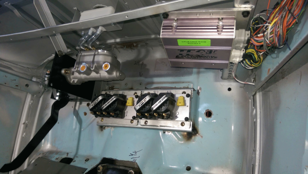
Showing the ECU (to the right), the coil packs and the 90 degree under dash brake master cylinder with the remote fille mounted under the old gas cap. Remove the gas cap and the reservoir is right there for filling.
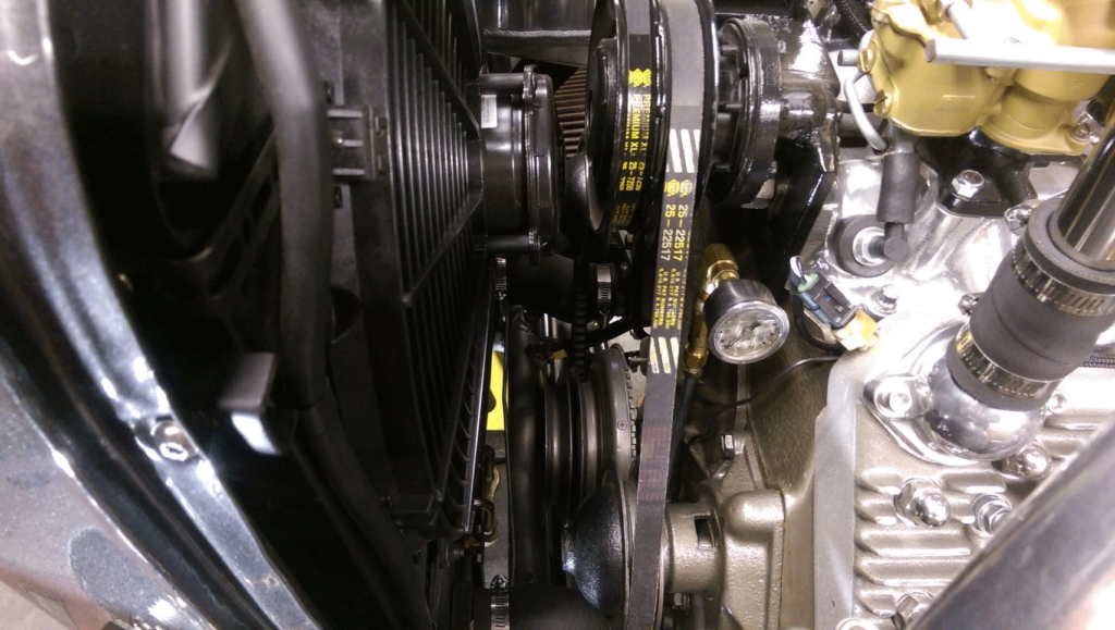
Showing the fuel pressure gauge.
Was this article a help? Consider supporting the Flat-Spot by becoming a Premium Member. Members get discounts with well known retailers, a cool membership packet full of goodies and your membership goes toward helping us upkeep and expand on this great archive.

