
1932 V8 FORD INSTRUCTION BOOK

V8 FOREWORD
This section contains information necessary to the proper care and operation of the Ford car. For your convenience, we have combined operational suggestions and advice on avoiding common abuses in the section titled ‘The Owner’s Responsibilities’. Read it carefully. Attention to the suggestions offered will go far to increase your enjoyment and satisfaction with the car. We have provided our customers with a complete set of driving instructions. To insure uninterrupted service, it is recommended that you have your lubrication and maintenance work done by an authorized Ford dealer. However, for owners who are unable to take their car to an authorized Ford dealership for lubrication and maintenance service, these instructions have been combined into one article. To reduce the possibility of any points being overlooked. The various units of the car are explained in detail. When repairs or replacements are necessary, it is important to use genuine Ford parts and have the work performed by competent mechanics. Expert workmanship is just as essential in servicing your car as it is in building it. Authorized Ford dealers employ factory-trained mechanics and use only genuine parts. To locate the nearest Ford dealer and authorized service station, consult your classified telephone directory under “Ford.”
V8 Specifications & License Data
- Engine: 90 degree, 8-cylinder, V-type
- Cylinder Bore ………………….. 3 / 6 inch
- Stroke………………………………. 3¾ inch
- Horsepower (S.A.E. rating) ………. 30
- Transmission: Synchronized selective sliding type with helical constant mesh gears in second speed. Three speeds forward, and reverse.
- Clutch: Single plate dry disc with mechanical damper.
- Brakes: Four wheel, internal expanding brakes operated by the foot brake pedal and the hand brake lever. Total braking surface 186 square inches.
- Steering Gear: ¾ irreversible-hour glass worm and sector type. Ratio 13 to 1.
- Oiling System: Engine lubricated by positive displacement gear pump direct to crankshaft main and connecting rod bearings, and camshaft bearings, by splash to balance of engine. Oil pan capacity 5 quarts.
- Cooling System: Thermo-syphon, pump accelerated-capacity 22 quarts.
- Fuel System: Tank capacity 14 gallons. Hydrostatic fuel gauge. Automatic downdraft carburetor Diaphragm type fuel pump.
- Rear Axle: ¾ floating type with torque tube drive. Spiral bevel drive pinion and gear.
- Tires: 18 x 5.25-pressure 35 pounds.
- Wheelbase: 106 inches.
- Turning Circle: 39 feet
- Tread: 56 inches.
- Road Clearance : 9 inches.
- Engine Number: The engine number is also the serial number of the car. The number is stamped on top of the clutch housing, also on the frame side member in front of left dash bracket.
The Owners Responsibility
The car has been designed and built so that it will furnish a safe, comfortable, carefree and economical means of transportation for many thousands of miles. However, no amount of engineering ingenuity or care in the manufacture can take the place of reasonable care and an avoidance of malpractices by the driver.
In addition to familiarizing yourself with the controls, familiarity with the points requiring periodic attention to maintain their efficiency is essential.
It is recommended that when these services are required you take the car to an authorized FORD dealer.
The following suggestions are offered to assist you in the operation of the car:
When shifting gears, move the gear shift lever as far as it will go. This will hold wear of the gears to a minimum.
Avoid driving with your foot resting on the clutch pedal as this may cause the clutch to slip, causing premature wear of the facings and the clutch release bearing.
Maintain a pressure of 35 pounds in the tires not only to reduce tire wear and save fuel but as a safety measure to improve braking and steering.
The cooling system should be protected from freezing in winter by the use of an anti-freeze.
Do not use boots in the tires, on the front wheels. The boots destroy the tires balance and are a constant menace to your safety when the car is operated at the higher speeds. Neglect of the body or the mechanical parts of the car will shorten their life and accelerate the rate of depreciation in the value of the car.
Shock absorbers contribute to your safety as well as your comfort and should be occasionally checked and the fluid replenished.
Strong door, steering and ignition locks are provided. Lock the car when parking. Use the inside door locks particularly when driving on lonely roads.
Always keep sufficient oil in the crankcase of the engine.
When driving with the windshield open, tighten the knurled nut on BOTH sides of the windshield. Driving with only one side of the windshield fastened subjects the glass to severe strains.
In zero weather the running of the motor for approximately one minute before turning on the lights will reduce the possibility of their burning out while the generator charging rate is adjusting itself to the high resistance offered by the cold battery.
Periodic chassis lubrication is an economical preventive of premature wear of the mechanical parts. The finish of the body and fenders should be protected from the elements by a suitable body polish. The twice yearly application of Lincoln polishing wax will provide excellent protection, preserving the original luster and beauty.
A new machine requires more careful attention during the first few days it is being driven than after the parts have been thoroughly “worked in.” To obtain best results, a new car should not be driven faster than 35 miles per hour for the first 500 miles.
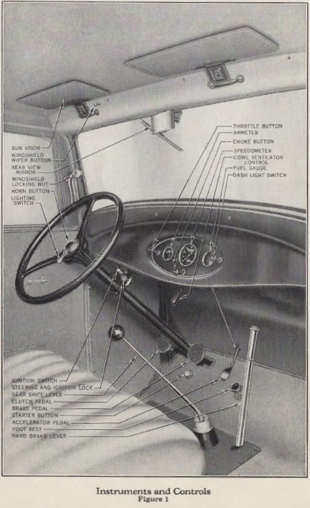
Instruments & Controls
The instruments and controls used in the operation of the car are shown in Fig. 1.
The Throttle Button is located on the instrument panel at the extreme left. Pulling the button out opens the throttle so as to maintain any desired engine speed on the road without depressing the accelerator pedal. Pushing the throttle button in closes the throttle and reduces the engine speed to idling speed as set on carburetor.
It is not necessary to use the throttle button for starting as the choke button automatically opens the throttle the correct amount for starting.
The Choke Button is located on the instrument panel. Pulling the button out closes t he choke valve in the carburetor, permitting a rich gasoline mixture to be drawn into the cylinders for cold weather starting. The richness of the mixture is in direct proportion to the extent to which you pull the choke button out. The engine should never be operated with the choke button pulled out after it has warmed up.
The Starter Button is located on the floor board under the steering column; pressing downward on the button closes the starter circuit and the starting motor will crank the engine. The button will return to normal position, opening the starter circuit, when released.
The Accelerator Pedal controls the amount of the fuel and air mixture entering the cylinders by opening the throttle valve in the carburetor. This pedal also operates t he accelerating pump in the carburetor. Quick downward pressure on this pedal causes a spray of fuel to be injected into the carburetor throat for maximum acceleration. Avoid depressing this pedal rapidly if the engine should stall when warm as this spray may flood the engine and make restarting difficult.
The Ammeter, located to the left of the speedometer, indicates “charge” when the generator is charging the battery. Caution: the average charging rate should not exceed 10 amperes. If ammeter shows an excessive rate your Ford dealer should be consulted. If the engine is running above 15 miles per hour and the ammeter does not register “charge” when the lights are “off” consult a Ford dealer.
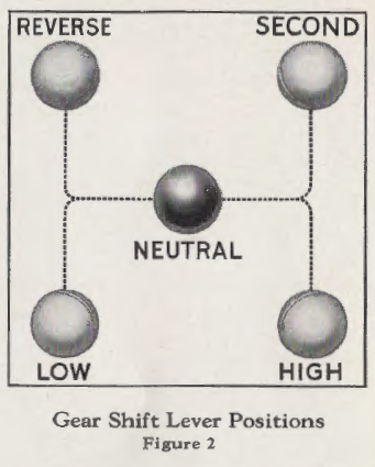
The Gear Shift Lever permits the selection of the gear reduction required. The gear shift positions are arranged in the conventional manner (see Fig. 2). The lever should always be in neutral position when starting the engine.
The Clutch Pedal provides control of the clutch engagement. Avoid resting your foot on this pedal when driving.
The Brake Pedal and Hand Lever both control the brakes on all wheels. Pull the hand brake lever back when parking, particularly on inclines.
When releasing the hand brake lever press downward on the foot pedal. This will remove the tension and permit the pawl to be withdrawn from the ratchet freely and assist in releasing the brakes.
The Spark Control on the Ford car is entirely automatic and requires no attention other than the original adjustment
made at time of manufacture. It is so designed as to automatically advance the spark by means of a centrifugal governor in proportion to the speed of the engine and to automatically retard the spark under load in direct proportion to the load.
The Windshield Wiper Button is located just above the windshield in front of the driver’s seat. When pulled back the windshield wiper is “on” and will operate when the engine is running. The action of the wiper may be slowed up by pushing the button in slightly.
The Rear View Mirror is readily adjustable to suit the driver’s requirements. Being held in position by a friction surface it may be adjusted to the desired angle at will.
The Speedometer, located in the center of the instrument panel, in addition to indicating the speed of the car registers the accumulated mileage, which may be used as a guide for periodic lubrication and maintenance requirements. .
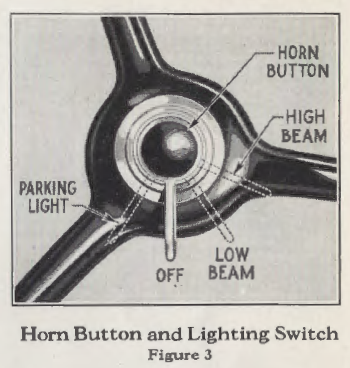
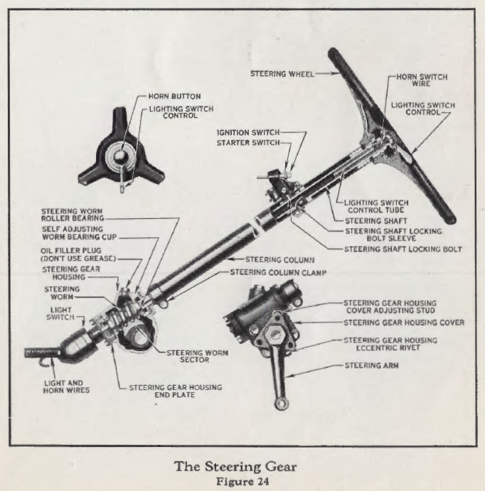
The Horn Button is located on the top of the steering column in the center of the steering wheel (see Fig. 3).
The Lighting Switch is located on the top of the steering column in the center of the steering wheel. When handle points straight back the lights are “off.” Moving the handle to the right or left closes the various circuits
(see Fig. 3). The instrument panel light and tail light circuits are also controlled by this switch.
The Fuel Gauge, located to the right of the speedometer, indicates the level of the fuel in the rear tank.
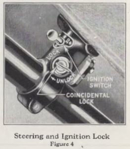
Theft Proof Lock: The Ford car is equipped with a coincidental lock built into the steering column bracket which supports the steering column at the instrument board; with one operation this coincidental lock locks both the steering gear and the ignition system (see Fig. 4). To shut off the engine, the ignition switch on the top of this bracket, directly in front of the steering column, should be pushed to the left to the “off” position. This motion opens the ignition circuit. The key is then turned in a counter-clockwise direction. This operation causes the locking bolt to be pushed toward the steering column either compressing the spring behind the lock bolt or actually engaging the slot in the steel sleeve on the steering column shaft, depending upon the position of the steering wheel. If the spring behind the locking bolt, is compressed the locking bolt automatically engages in the slot in the steel sleeve on the shaft as soon as the steering wheel is revolved.
The wheel can be locked either with the front wheels straight ahead or hard over to either the right or left. The ignition switch is locked as soon as the key is turned in the lock regardless of the position of the steering wheel and the key can be removed. Turning the key one-half turn clockwise withdraws the locking bolt from the steel sleeve in the steering shaft and at the same time unlocks the ignition switch. To turn on the ignition current the ignition button is pulled to the right to the position marked “ON.” If the key turns quite hard in the lock moving the steering wheel slightly will relieve the pressure on the locking bolt and permit the key to turn freely.
Starting The Engine
(1) Unlock the coincidental lock on the steering column bracket by turning the key one-half turn in a clockwise direction.
(2) Push the ignition switch lever to the right-to position marked “on” (see Fig. 4).
(3) Be sure the gear shift lever is in neutral position (the position in which it can be moved freely from side to
side) .
( 4) Pull the choke button out. If the engine is cold pull the choke button all the way out.
(5) Press on the starter button. (In cold weather the starter will crank the engine more easily if the clutch is
disengaged.)
(6) As soon as the engine starts remove your foot from Steering and Ignition Lock the starter button. Figure “4,
(7) Push the choke button in as far as possible without disturbing the smooth performance of the engine. As soon as the engine is warm push the button all the way in.
Important
When starting a warm engine do not pull the choke button out unless the engine fails to start on the normal mixture as there is a possibility of flooding the engine with an over rich mixture of gas. If you should by accident flood the engine, pull the throttle button out slowly and with a choke button in normal position crank the engine a few revolutions with the starter to exhaust the rich gas. Avoid moving the accelerator pedal while exhausting the rich gases, as any quick movement of the accelerator would cause the accelerating pump to inject a spray of fuel into the carburetor throat, which would increase the fuel in the already flooded engine and make restarting difficult.
Driving the Car
Before starting the car, familiarize yourself with the various instruments and controls as covered.
(1) Start the engine. (See page 14 for full instructions.)
(2) Release the hand brake lever.
(3) Disengage the clutch by pushing down the clutch pedal.
(4) l\love the gear shift lever to low speed position.
(5) Gradually release pressure on the clutch pedal allowing it to return to normal position. At the same time depress the accelerator pedal, increasing the engine speed (as you engage the clutch the car will move forward).
(6) When the car has reached a speed of five to eight miles
per hour remove your foot from the accelerator, disengage the
clutch.
(7) Move the gear shift lever to second speed position.
(8) Again engage the clutch, increasing the engine speed as required.
(9) When the car has reached a speed of 12 to 15 miles per hour remove your foot from the accelerator, disengage the clutch.
(10) Move the gear shift lever to high speed position.
(11) Again engage the clutch. Depress the accelerator pedal increasing the speed of the engine, and the car, to the speed desired.
(12) To shift from high to second gear at any speed merely disengage the clutch and make the shift with no hesitation
in neutral. However, if the shift is made at high car speeds, the movement of the gear shift lever should be made quickly with no hesitation in neutral while a more deliberate movement is required for the final engagement.
(13) To utilize the braking action of the engine in any speed remove your foot from the accelerator pedal leaving the
clutch engaged.
(14) To stop the car remove the foot from the accelerator and depress the clutch and brake pedals as required.
(15) To reverse the car (the car must be brought to a stop before attempting to reverse its direction). With the foot off of the accelerator pedal and the clutch disengaged, move the gear shift lever to the reverse position, engage the clutch and depress the accelerator pedal as required.
(16) To stop the car in reverse remove the foot from the accelerator and depress the clutch and brake pedal as required.
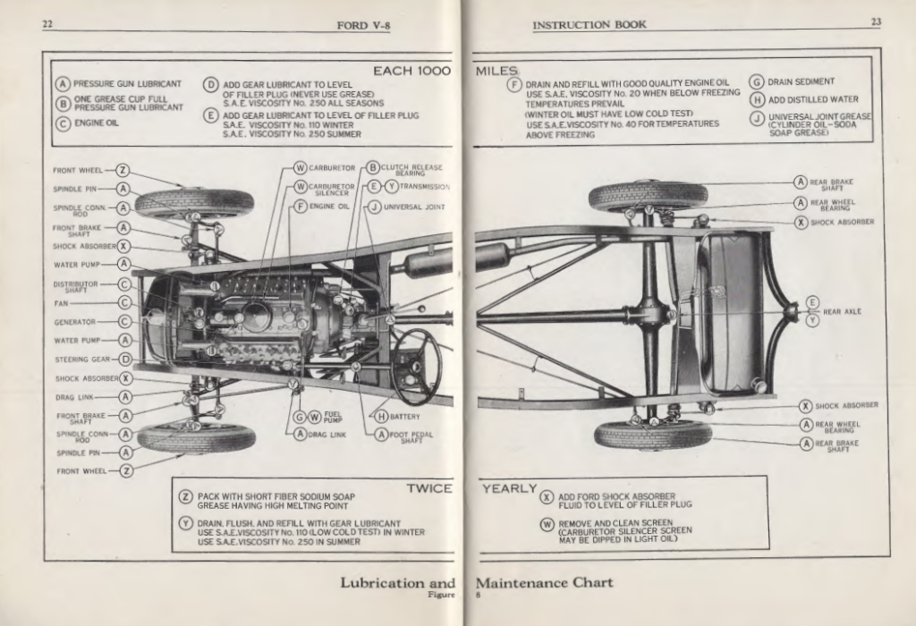
Lubrication and Maintenance
The importance of proper lubrication and periodic inspection and adjustments cannot be over-emphasized. The lubrication and maintenance work on the Ford eight-cylinder cars can be divided into two groups; first, points requiring attention every 1000 miles; second, points requiring attention twice yearly or every 5,000 miles (whichever occurs first). The lubrication chart on pages 22 and 23 gives full information for the complete lubrication of the Ford car. Proper lubrication has a vital effect on the life of your car; consequently you should follow these instructions very carefully. All Ford dealers arc equipped to render this lubrication and maintenance service to your car.
Engine Lubrication
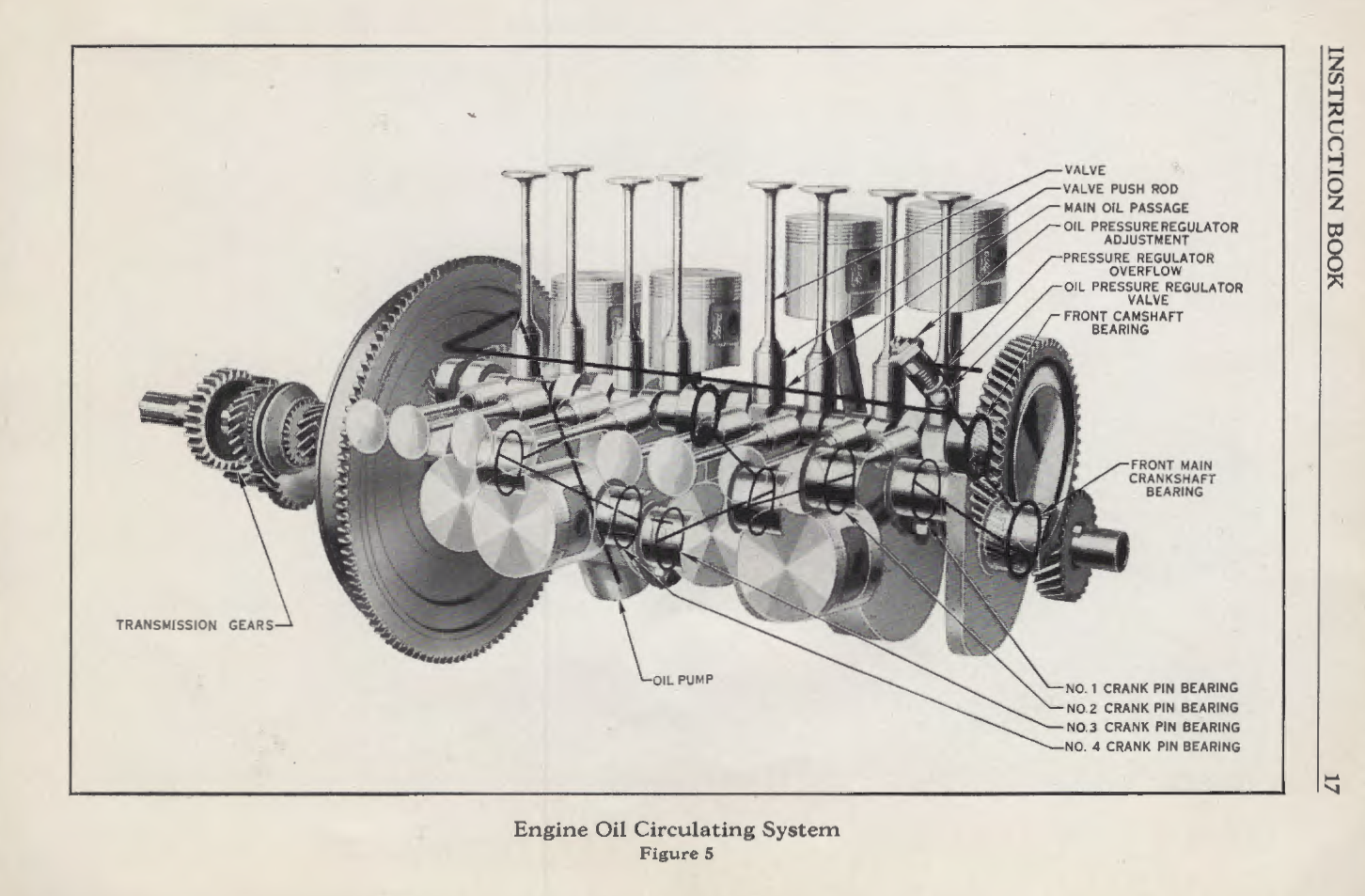
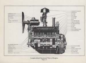
All parts of the engine arc lubricated from the oil reservoir in the oil pan by positive displacement gear pump to all crankshaft, main and connecting rod bearings and camshaft bearings, and by splash to the balance of the motor (see Fig. 5).
It is advisable to clean out the oil pan by draining off the old oil when the new car has been driven 300 miles, and again when a total mileage of 1000 miles has been reached and at each 1000 miles thereafter. The oil will drain out more completely if warm, and should be replaced with 5 quarts of engine oil of the proper viscosity and quality.
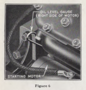
The oil level should be checked at least every 200 miles, and additional oil added when required to bring it to the proper level. Since more oil is consumed by the engine at the higher engine speeds, its level must be watched closely when the engine is operated under sustained high speeds. To determine the correct oil level, use the indicator located on the right side of the engine at the rear (see Fig. 6), as follows: Pull the indicator-wipe it off-re-insert the indicator and again remove it.
The mark made by the oil indicates its level. When the oil reaches the point marked “F” on the indicator, it is at the maximum level. Under no circumstances should the oil level be permitted to get below the point marked “L” as any attempt to run the engine with too little oil may seriously damage the engine. When replacing the oil level indicator, push the indicator all the way down. Failure to fully insert it in to the opening permits oil to escape.
Only high grade engine oil should be used in the engine. Oil of this kind reaches
the bearing surfaces with greater ease and cuts down frictional heat. It should have sufficient body so that the pressure between the bearing surfaces will not force out the oil and allow the metal to come in actual contact.
Inferior oils have a tendency to carbonize quickly, also “gum up” on the piston rings, valve stems and bearings. In cold weather a lighter grade of oil having a low cold test is absolutely essential for the proper lubrication of the engine. In general an oil having the body of S. A. E. viscosity No. 40 will prove satisfactory for summer use. For winter use, oil having the specifications of S. A. E. viscosity No. 20 should be used. It is essential, however, that this winter oil have a low cold test. It must be understood that these classifications are of “body” only and not of quality. It is also essential that the oil be otherwise properly refined.
The Chassis
The chassis should be lubricated after each 1000 miles of operation. For your convenience, it is suggested that the lubrication of the chassis and the changing of engine oil be performed by a Ford dealer at the same time.
Lubricating the Clutch Release Bearing
The clutch release bearing is lubricated through a grease cup, located at the right hand side of the clutch housing. After every 1000 miles of operation, the cup should be screwed in as far as it will go. This will force the lubricant into the bearing. The cup should then be backed off and repacked with a good grade of pressure gun lubricant and replaced, screwing it in 2½ to 3 turns. Note; the clutch is a dry disc clutch and under no circumstances should it be oiled.
Lubricating the Steering Gear
Every 1000 miles, remove the plug on the steering gear housing and add gear lubricant until it reaches the level of the filier plug hole. Use gear lubricant only, never use greases in the steering gear. A gear lubricant of S. A. E. viscosity No. 250 will be suitable for all seasons.
Oiling the Generator
The bearings in the generator are lubricated through a small oil hole, located at both ends of the generator. Fill with oil every 1000 miles.
Oiling the Distributor
Fill the oil cup at the front of the distributor every 1000 miles with engine oil.
Transmission
Each 1000 miles, sufficient transmission lubricant should be added to bring it level with the filler plug.
Rear Axle
Each 1000 miles, sufficient gear lubricant should be added to bring it level with filler plug.
Universal Joint
Each 1000 miles, the universal joint housing should be filled with a universal joint lubricant composed of cylinder oil,
thickened with sodium tallow soap. The universal joint housing cap is provided with a pressure gun lubricator fitting.
Lubricating the Car
In order to properly force lubricant to all parts equipped with the conical shaped lubricator fittings, a high pressure compressor gun is employed. With this gun, the lubricant can be forced in under a pressure of 2000 pounds or more per square inch, thus assuring a more thorough and positive lubrication than can be accomplished any other way.
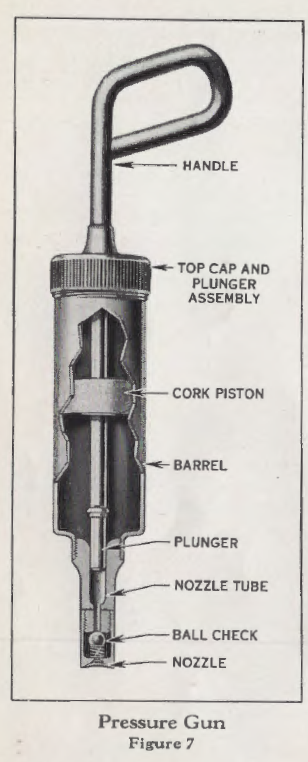
Ford dealers are equipped to render this service. However, a compress or gun is supplied with the tool equipment of each car, in case you cannot get to a Ford dealer. To fill the compressor, remove the cap and plunger (see Fig. 7).
Use a good grade of pressure gun lubricant for all bearings having the conical shaped lubricator fittings (except the universal joint), packing it solidly, avoiding air pockets. Fill only to the top of the lettering on the outside of the barrel.
Operating the Compressor
When the compressor is pressed against the conical shaped fittings, the plunger moves forward,
forcing the lubricant in the nozzle directly through the fitting into the bearing, under an extremely high pressure.
When the pressure on the handle is released, grasp the barrel of the compressor with one hand and draw back the handle with the other, so as to load the compressor and make it ready to deliver a charge of lubricant with the next forward thrust.
Springs
The springs should be sprayed with a penetrating oil.
Fuel Pump
Drain sediment from fuel pump by means of drain plug (see Fig. 13). In case of excessive water or sediment, drain accumulation from rear tank also.
Cylinder Head Nuts
After the first 300 miles of operation, the cylinder head nuts should be tightened. After this tightening, they will require no further attention unless head is removed.
Tires
Air pressure in tires should be checked and sufficient air be added to bring the pressure up to 35 pounds. Unequal tire pressure results in uneven braking action.
Radiator
Water and anti-freeze solution in the cooling system should be checked and replenished if required.
Lights It is advisable at this time to inspect the various lights on the car and replace any bulbs necessary.
Battery
Each 1000 miles, or every two weeks (whichever occurs first), inspect the battery and add sufficient distilled water to bring the electrolyte to the proper level. A rapid loss of water in the battery usually is an indication of an excessive charging rate, which should be corrected. (See page 52 for complete instructions.)
Starting Motor
The bearings in the starting motor are lubricated when they are installed in the car and require no further attention.
Twice each year, preferably in the fall and spring, in addition to all the lubrication and maintenance operations in Group I , the following operations are required:
Rear Axle Lubrication
Each fall and spring the lubricant in the rear axle should be drained and the housing flushed with kerosene. New lubricant should then be added until it reaches the level of the oil filler hole in the housing. Use the correct grade of lubricant to suit climatic conditions.
Lubricating the Transmission
Each fall and spring the gear lubricant should be drained from the transmission by removing the drain plug at bottom of transmission case. The interior of the transmission case should then be thoroughly flushed with kerosene and refilled with fresh gear lubricant of the correct grade. The new lubricant is poured into the transmission through
the filler hole, located at the right hand side of the transmission case. Pour sufficient lubricant in until it reaches the level of the filler hole.
Front Wheels
Twice yearly or every 5,000 miles (whichever occurs first), or at any time when the car has been operated with the front wheel inner hub cap missing, the front hubs should be removed and the bearings and the inside of the hub washed clean with kerosene and repacked with a short fiber sodium soap grease having a melting point of not less than 350° F .
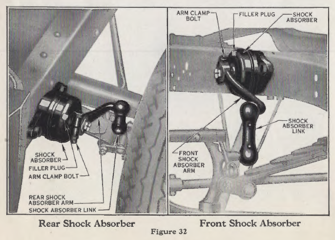
Shock Absorbers
Each fall and spring or every 5,000 miles (whichever occurs first), the level of the fluid in shock absorbers should be checked and sufficient fluid added until it reaches the level of the filler plug. The correct fluid may be secured from any authorized Ford dealer. Grease or engine oil should never be added to the shock absorber. If leakage is indicated, the packing should be adjusted or replaced.
Ignition
At each 5,000 miles, it is advisable to inspect the gaps between the breaker points as well as the spark plug gaps and adjust as required.
Battery
Inspect battery connections and clean if corroded.
Body Bolts
Inspect body bolts. If loose, they should he tightened.
Clutch
Check the amount of free travel of the clutch pedal and adjust
if required.
Brakes
Check the movement of the brake pedal, readjusting the
brakes if the pedal travels to within two inches of the floor
board when the brakes are applied.
Carburetor Silencer
Twice yearly or every 5,000 miles (whichever occurs first) , the screen should be removed from the carburetor silencer and washed in gasoline. After the gasoline has dried, dip the screen in engine oil and reinstall. Where the car is operated under extremely dusty conditions, it may be necessary to clean the silencer oftener. Operating the car with an excessively dirty silencer will cause high fuel consumption.
Fuel Pump
Clean the fuel pump screen.
Carburetor
Clean carburetor screen.
Body
A twice yearly application of Lincoln polishing wax will enhance and preserve the luster and beauty of the body and fenders.
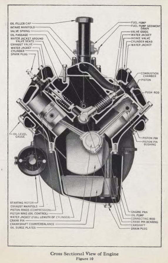
The Engine
In the designing and building of the Ford eight-cylinder engine, those features have been retained which were present on previous Ford engines that accounted for their efficiency, long life and world wide acceptance. Figures 9 and 10 are sectional views of the engine. The engine is of the 90 degree block with 90 degree crankshaft design.
The eight cylinders and crankcase are cast en bloc, assuring the permanence of the relative locations of the reciprocating parts.
Camshaft
The camshaft is driven by a helical cut gear on the crankshaft, thus eliminating the need of a timing chain or idle gears and the consequent adjustments. The circuit breaker and distributor is driven by the camshaft,
eliminating the necessity for shafts, gears, etc., and adjustments to compensate for wear.
Valves
The valve clearance is accurately set beyond the maximum expansion of the valve, with the engine cold without the use of · adjusting screws, etc. The specially developed Ford steels used in the valves make them able to withstand the high temperatures of sustained high speed without damage except where the ignition is late. Have the circuit breaker point gaps checked twice yearly or every 5000 miles and adjusted to compensate for wear of the breaker arm. The valves will in time require grinding. The time when this will become necessary cannot be foretold . However, when it is required, take the car to an authorized Ford dealer. All Ford dealers are equipped to duplicate the accurate work of the factory. Permitting the engine to idle long enough for the valves to cool before turning the ignition “off” will materially lengthen the life of the valve when the car is operated under sustained high speeds.
Trouble on the Road
We have anticipated as far as possible the various combinations of circumstances which would result in difficulty with the engine being experienced by Ford owners and have incorporated the design such features as to combat them. However, should trouble at any time be experienced, consult an authorized Ford dealer. If a dealer is not readily available, a process of elimination will isolate the cause and the remedy will suggest itself.
To Operate the Engine Requires:
A fuel system which provides a mixture of gasoline and air for the engine.
An ignition system to provide a spark at the spark plug points to ignite the fuel air mixture.
A cooling system to prevent overheating.
An oiling system to reduce frictional heat and prevent seizure of the working parts.
Each of these systems are explained in detail elsewhere in this section.
To Isolate the Cause of the Trouble,
proceed as follows: A quick stroke of the throttle lever on the carburetor should produce a spray of gasoline in the carburetor throat. If this is not noted, sufficient fuel is not being supplied to the carburetor. (It will be necessary to remove the carburetor silencer and push down the carburetor vanes to make this test. ) (See Fig. 14.) After several strokes, the carburetor bowl will be empty and the spray will no longer be noted. However, if the first strokes produce this spray, the carburetor is receiving fuel.
A spark should be produced at each spark plug once for every two revolutions of the engine, whether crank by hand or the starting motor. To t est, touch a wooden handled screwdriver to the cylinder head and the spark plug nut while engine is cranked. If a spark is not noted, the ignition system is at fault.
If the engine overheats, check the oil level in the engine and the water level in the radiator and replenish each as required. However, if the water is extremely low, allow the engine to cool off before adding water to prevent the sudden contraction of the cylinders, by the cold water, from cracking them.
Should the performance of the engine at any time become sluggish or noisy, consult any authorized Ford dealer. You will find them highly efficient and with an earnest desire to serve you, and the possibility of trouble on the road will be remote.
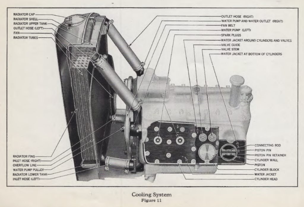
The Cooling System
The Ford engine is cooled by a circulation of water through the water jackets which surround the cylinders, combustion champers, and valve seats. The water is circulated by thermo-syphon action, the flow of water being accelerated by means of centrifugal water pumps located at the front of each cylinder head. These pumps draw the heated water from the engine into the upper radiator tank, from which it flows downward through numerous tubes to the lower radiator tank and back to the water jackets of the engine. An arrangement of fins around the radiator tubes effectively carry off the heat of the water as it passes through them. The heat is then radiated from these fins into the current of air drawn in by a fan located just back of the radiator.
To prevent overheating keep the radiator ,Yell filled.
Radiator
As the proper cooling of the engine is dependent upon the water supply, it is important particularly with a new car to see t hat the radiator is kept well filled.
Cleaning the Cooling System
The entire system should occasionally he flushed out. To do this, open the drain plugs (on the side of each bank of cylinders, at the front, below the water inlet connection) and insert a hose into the filler neck, allowing the water to flow through the system for about fifteen minutes or until the water comes out clear.
Care of the Cooling System in Winter
In freezing weather it is necessary to use an anti-freeze solution in the system to prevent freezing of the water.
Do not overlook the fact that constant evaporation will eventually weaken most anti-freeze solutions, consequently
they should be tested frequently, especially in severe weather. A suit.able anti-freeze solution can be obtained from any authorized Ford dealer, also complete directions as to the percentage of solution to be used to withstand the various low temperatures. If an anti-freeze solution is used that contains alcohol, be careful when filling the radiator not to spill any of the solution, as it may damage the paint. After filling the radiator, be sure the radiator cap is replaced tightly.
Adjusting the Fan Belt
The fan, water pumps, and generator are operated by the same “V” shaped belt. The belt is adjusted to the proper tension when the car leaves the factory and this adjustment should not be changed unless the belt slips. The adjustment is made by loosening the generator support to engine clamp bolt and moving the generator upward by turning the adjusting nut. Do not tighten the belt more than is actually necessary to keep it from slipping. Permit a Ford dealer to check the adjustment as soon as possible.
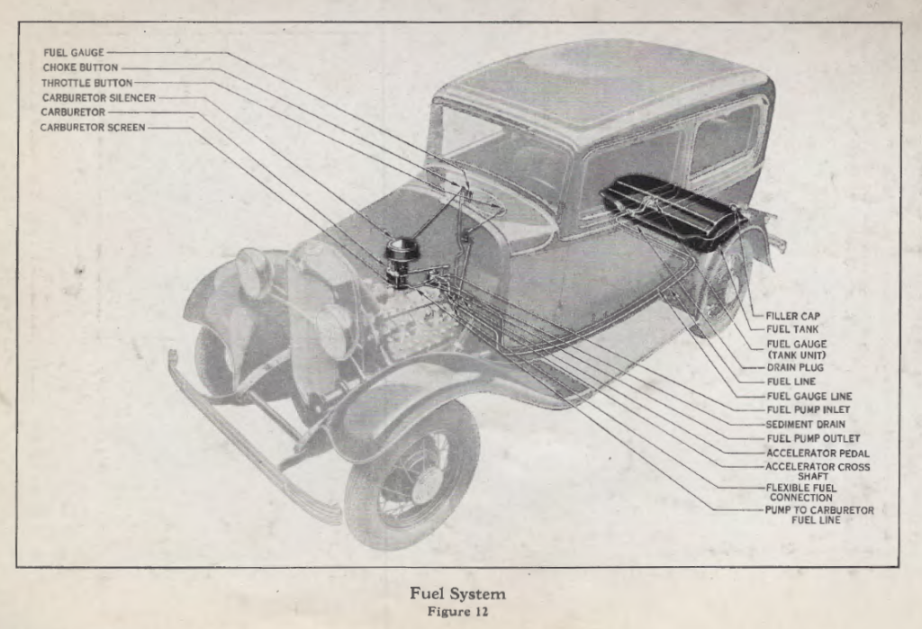
Fuel System
The gasoline is carried in a 14 gallon tank mounted on the frame at the rear of the car. From this tank the gasoline is drawn to the fuel pump. From this pump the gasoline is pumped to the carburetor where it is mixed with air and drawn into the cylinders by piston suction. The level of the gasoline in the tank is indicated by the gauge on the instrument panel.
Gasoline Tank
The gasoline may be drained by removing the plug at the bottom of the tank. The tank is provided with a trap to catch water or sediment which should occasionally be run off through this hole.
Gasoline Gauge
The hydrostatic fuel gauge mounted on the instrument panel indicates the amount of fuel in the tank at the rear of the car and is operated by pressure of the gasoline on air trapped in an air bell submerged in the tank. Being self-correcting and entirely automatic in action, it requires no attention other than the keeping of the fuel gauge line connections tight.
If at any time the level of the fluid in the gauge fluctuates with acceleration or sudden stops it is no doubt caused by the presence of water in the line, caused by condensation, in which case consult an authorized Ford dealer.
If at any time for any reason it is necessary through loss to replace the fluid in the gauge it should be secured from an authorized Ford dealer, as the accuracy of the gauge is dependent on the specific gravity of the fluid used.
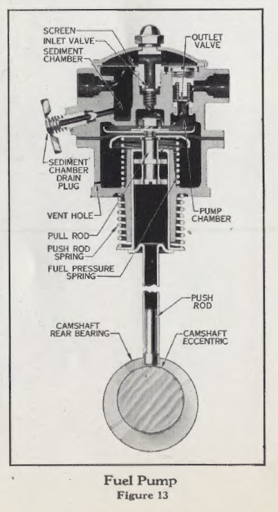
Fuel Pump
The fuel pump is located on the top of the engine behind the carburetor and is driven by an eccentric on the camshaft (see Fig. 13). It draws the gasoline from the tank and supplies it to the carburetor. Being automatic in action, the pump requires little attention other than to keep it free from dirt and keep all connections tight. The construction of the pump is such as to provide a trap for sediment or water which can be drained off by means of the drain plug on the side of the pump.
If at any time the carburetor is not receiving sufficient gasoline one of the following is likely to be the cause:
(1) Fuel tank is empty.
(2) Screen has become fouled with sediment, in which case it should be cleaned.
(3) The gasoline line or its connections have a leak at some point, permitting the entrance of air to the line. The remedy, of course, being to stop the leak, at which time the pump will prime itself and again function properly. Cranking the engine for 20 seconds with the starter should prime the pump.
(4) If at any time gasoline is seeping through the small hole shown in lower half of fuel pump (see Fig. 13) it is probably an indication of the diaphragm in the pump having become worn. While this does not usually render the pump inoperative immediately, it is advisable to replace the diaphragm as soon as possible. Ford dealers carry these parts in stock and it is recommended that you consult them should repairs be required.
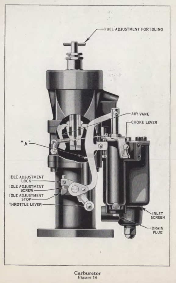
Carburetor
The carburetor is of the down draft type with accelerating pump, sleeve valve choke, and air vane operated main fuel supply jet. The carburetor is entirely automatic in action. All adjustments are made at time of manufacture and will remain permanently correct unless tampered with.
Consult your Ford dealer should the car’s operation indicate an adjustment is necessary.
To Test the Fuel System
In case of trouble on the road, remove the silencer, push clown on the air vane (see Fig. 14) with a pencil or stick. ·work the throttle lever several quick strokes by hand. A stream of gasoline should be produced at the encl of the tubing (“A,” Fig. 14).
Should this test indicate that the carburetor is not receiving sufficient fuel, the screen (see Fig. 14) should be examined and cleaned. It will probably be advisable to clean the- fuel pump screen also (see Fig. 13). If the cleaning of these screens does not correct the trouble, the fuel pump and fuel line should he examined (see page 34).
It is not necessary to pull out the throttle button when starting the engine as the throttle automatically opens the correct amount for starting when the choke button is pulled out.
Silencer
Too rich a fuel-air mixture, as indicated by sluggish performance and black exhaust gases, may indicate a clogged screen in the carburetor silencer. If the car is operated under extremely dusty conditions, it will be necessary to clean this silencer screen frequently.
The Clutch
The clutch on the Ford V-8 car is of single plate, dry disc type with mechanical damper operated by the foot pedal. The clutch is the medium through which the power of the engine is delivered to or cut off from the transmission.
Mechanical Damper
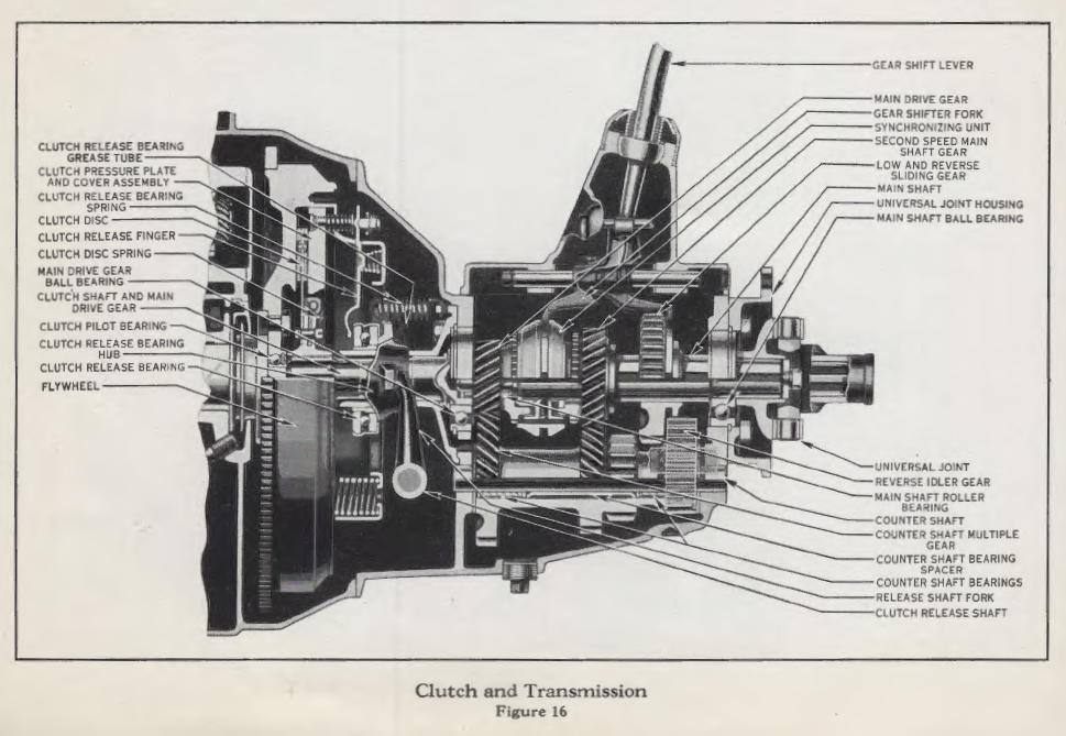
When driving power is applied a certain amount of restrained movement exists between the clutch disc hub and the clutch disc proper, caused by the flexing of the clutch disc springs (Fig. 16). The clutch disc by virtue of this mechanical construction smooths out and stabilizes the flow of power through the entire range of acceleration and deceleration.
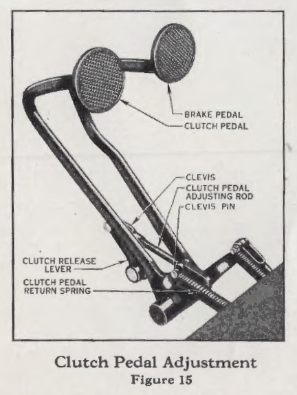
Fig. 16 illustrates the arrangement of the component parts of the clutch and transmission.
Adjustment
The clearance between the clutch release bearing and the clutch plate release fingers must be maintained at all times and is indicated by the amount of free travel of the clutch pedal. As the clutch disc facings become worn, it will be necessary to adjust this clearance. The correct adjustment is when the clutch pedal has one inch free movement. This adjustment is easily made by removing the clevis pin (see Fig. 15) and turning the release arm rod. Screwing the rod out decreases the clutch pedal free movement. Screwing the rod in increases the amount of free movement. After making the adjustment, be sure to replace the clevis pin and cotter key. It is recommended that an authorized Ford dealer make this adjustment should it in time be required.
Abuse
Driving with your foot resting on the clutch pedal, commonly referred to as “riding the pedal,” will result in excessive wear of the release bearing and clutch disc facings, and necessitate frequent adjustment and may in time necessitate refacing the clutch disc.
The Clutch Release Bearing
The clutch release bearing is of an exceptionally sturdy design, lubricated by means of a grease cup located at the light side of the transmission case, and through a flexible tube running to the bearing. Each 1,000 miles of operation the cup should be screwed down as far as it will go. This will force the lubricant into the bearings.
Transmission
The transmission in the Ford car is of the selective sliding type with silent running constant mesh gears in second speed. All gears used in second speed having helical teeth to insure their quiet operation.
With the gear shift lever in high speed position the drive is direct.
A synchronizer is used to insure quiet and easy gear engagement between high and second gear. Fig.16 shows the transmission used in the Ford V-8 car. Portions of the case and the gears have been cut away to better illustrate the various gears, synchronizer, bearings, etc., used. The reverse idler gear has been drawn semi-transparent to permit the counter shaft reverse gear, which is on the other side of it, to be shown.
The power is transmitted entirely on roller or ball bearings in all forward speeds and, with the exception of the reverse idler gear, in reverse gear also.
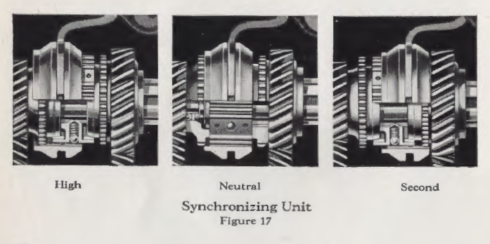
The Synchronizing Device
Makes shifting smooth, quiet and almost effortless. It consists of a hub and ring. Teeth on the inside of the ring mesh with teeth on the outside of the hub at all times. In neutral position the central location of the ring on the hub is maintained by six steel balls held in a groove in the ring by springs. The hub is built with a bronze section on each side which fits the conical steel flange on either second or high gear. When a shift is made to either high or second speed, the synchronizing device moves as a unit until the bronze section of the hub contacts the conical flange of the gear. Acting as a conical clutch the speed of the two is synchronized or made uniform and, as the shift is completed, the internal gear or ring of the synchronizer unit is released from its centrally located position on the hub and the teeth engage in the teeth of the high or second speed gear. As the two are rotating at the same speed the meshing of these gears is effected without clashing of the teeth. Fig. 17 shows the operating positions of the synchronizer unit in high and second speed drive as well as neutral position.
Care
Only a fluid gear lubricant should be used in the transmission, the level of which should be maintained at the height of the filler plug, located on the right side of the transmission case. Too high a level of lubricant in the transmission “ill result in its seepage past the bearings and clown the torque tube to the rear axle. Too low a level will accelerate the wear of the component parts. Releasing of the clutch when starting the motor will decrease the draw on the battery and assist starting, particularly in cold weather.
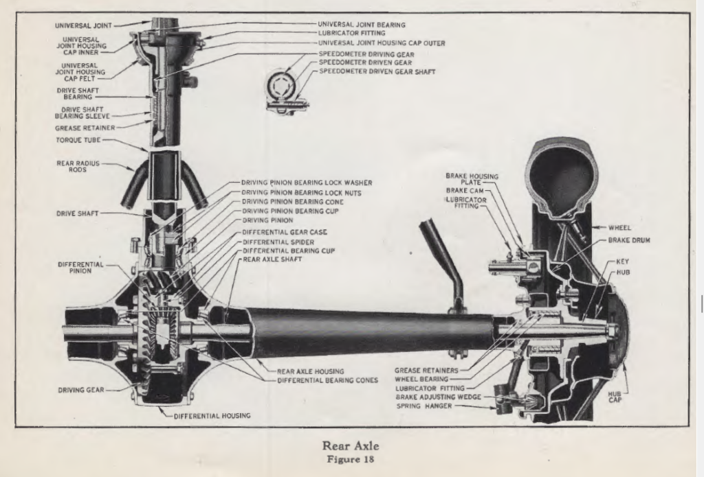
The Rear Axle
The power is transmitted to the rear axle from the transmission) by means of a universal joint and a drive shaft running on roller bearings. The load is carried on the axle housing, thus freeing the axle shafts of all strain other than the actual transmission of power. All road thrust is delivered through a torque tube to the frame. Owing to the high degree of accuracy obtained by the use of special Ford developed machinery the various dimensions of the component parts of the axle are held to such fine limits that adjustments are not required. Gear back lash and bearing clearances arc permanently correct. The axle shaft nut which holds the hub in place should be kept tight at all times to prevent damage to the taper on either the axle shaft or hub.
The Front Axle
The front axle of the Ford car is so designed as to afford maximum safety at either high or low speeds on rough roads or pavements. The axle is held in position by radius rods pivoting on the frame cross member. This method of mounting holds the axle in the correct position with regards to brake rods, steering connections, and spindle pin inclination at all times regardless of the road or speed of the car. In normal service the only attentions required are lubrication and the correct adjustment of the various steering connections. It is recommended that these adjustments when required be made by an authorized Ford dealer.
The front wheels should be jacked up periodically and tested for smoothness of running and excessive side play. To determine if there is excessive side play, grasp the sides of the tire and shake the wheel. Do not mistake loose spindle bushings for loose bearings. Insert a wedge between spindle and axle when making this test to take up any spindle bushing play. If the spindle bushings have become worn sufficiently to warrant it, they should be replaced. Consult a Ford dealer.
Adjusting Front Wheel Bearing
If there is excessive play in the bearing it can be adjusted as follows :
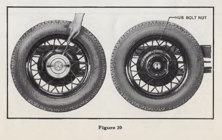
Jack up front of car and with a screwdriver remove outer huh cap as shown in Fig. 20.
Remove the front wheel.
The inner hub cap may now be removed by turning in a counter-clockwise direction. By removing the cotler key the front wheel bearing nut, bearings and hub may be removed or adjusted.
When reassembling or adjusting the adjusting nut should be run up tight and then turned back approximately ¼ turn and the cotter pin replaced. Both the inner and outer hub caps should again be installed. Never operate the car with the front hub caps missing.
Ford Steel Spoke Drop Center Wheels
The Ford cars are equipped with sturdy steel spoke wheels of accurate balance. The hub, rim, and steel spokes are electrically welded into one piece and require no attention other than correct installation on the hub and the correct installation of the tire so as not to destroy the balance of the wheel.
To remove the wheels jack up the side of the axle from which the wheel is to be removed. With a screw driver remove the hub caps as shown in Fig. 20. With the wrench incorporated in the starting crank remove the five hub bolt nuts. The wheel can then be removed.
When replacing a wheel, tighten each hub bolt nut a few turns at a time. Then follow around the hub, tightening each
nut firmly. If nuts are not drawn up evenly, the wheel will not run true.
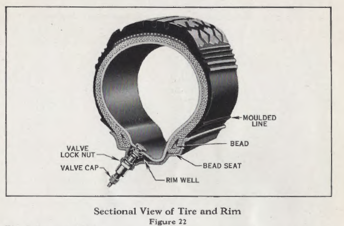
To Remove Tire
(1) Deflate the tube completely.
(2) Remove the valve cap and valve lock nut. Loosen both beads from the bead seats.
(4) Force the outside bead from the bead seat into the rim well at a point opposite the valve.
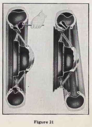
(5) With two tire tools placed approximately four inches on each side of valve lift the bead over the rim
flange (see Fig. 21).
(6) Follow around the flange with the tools until the outside bead is free from the top.
(7) Force the inside bead into the rim well at the top.
(8) Pull out bottom of the tire until it swings clear, as shown in Fig. 21.
To Mount Tire
(1) Inflate the tube until barely rounded out and insert in tire. The tires are marked with a red dot to insure correct balance. The tube must be placed in the tire with the valve stem at point marked.
Caution: Never use a tire flap. Use only tires having balancing dot and molded line for centering on the
wheel.
(2) Place the tire on the wheel, guiding the valve through the valve hole.
(3) Push the inside bead into the rim well at a point next to the valve.
(4) Force the remaining portion of the bead over the outside flange of the rim. If a tire tool is used, do not attempt to force too large a portion over the flange at one time.
(5) Apply the valve lock nut loosely.
(6) Lift up on the tire, placing the outside bead in the rim well at the valve.
(7) Starting at either side of the valve, force short lengths of the bead over the flange, continuing around the wheel until the entire bead is in place. Always keep as much of the bead as possible in the rim well while applying.
(8) Before inflating, remove the valve lock nut and push the valve stem into the casing as far as possible to make certain that the tube is not pinched under the tire bead. Do not let go of the valve stem while doing this.
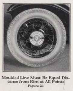
(9) Reapply rim nut, and inflate the tube to not more than two pounds pressure, working casing back and forth
to insure proper setting of the tire. The proper setting is indicated by the molded line on the tire being equally
spaced from the rim at all points (see Fig. 23).
(10) Inflate the tire to 35 pounds pressure. With Ford steel spoke wheels, tires can be more easily changed with wheel mounted on axle or tire carrier than by Figure 23 laying the wheel on ground.
Keep Tires Inflated to 35 Pounds
Tires should never be run partially inflated, as the side walls are unduly bent and the fabric is subjected to stresses which cause what is known as rim cutting. Keep both front and rear tires inflated to 35 pounds, and check the pressure once a week. The air pressure in the tires has a very pronounced effect on the action of the brakes, as well as the correct operation of the front wheels and steering gear. Never run on a flat tire, even for a short distance. Skidding also shortens the life of the tires. A void running in street car tracks, or bumping the sides of the tire against the curbing.
The Steering Gear
The steering gear on the Ford car is of the “hour glass” worm and sector type. The worm rotates on self-adjusting tapered roller bearings and requires little attention other than periodic lubrication. Means of adjustment to compensate for wear are provided. These adjustments, however, should not be attempted by the layman, and it is recommended that, when they arc required, you consult a Ford dealer.
Brakes
The braking system includes four internal expanding brakes, one at each wheel, operated by the foot brake pedal and the hand brake lever. The brakes are mechanically operated design of simple construction insuring quiet and positive action and highest efficiency at all times.
Adjusting Brakes
Before attempting to adjust the brakes, equalize the air pressure in the tires. The most effective method of testing the brakes is by an actual road test. When, with the tires all inflated to 35 pounds pressure, a road test reveals the braking action to be unequal at the various wheels or the pedal travel is to within two inches of the floor board, the brakes should be adjusted. Authorized Ford dealers can make this adjustment correctly and quickly at low cost .
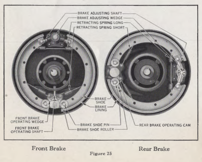
Don’t jeopardize your safety by makeshift adjustments. If a Ford dealer is not available, a temporary adjustment may be made by the screwing in of the adjusting screw provided at each wheel. One or two notches should be enough ordinarily. Always jack up the wheel to sec that the brakes do not drag after this adjustment. Allow your Ford dealer to check your adjustment as soon as possible.
Electrical System
The electrical system includes the following equipment:
Storage Battery……………….Spark Plugs
Generator……………….Ammeter
Starting Motor……………….Horn
Distributor and Circuit Breaker……………….Lights
Ignition Coil……………….Condenser
The Battery
The Ford electrical system uses a six-volt, SO-ampere-hour, 13-plate battery, designed and built to meet the requirements of the Ford car.
Adding Water to Battery
Every two weeks check the electrolyte in the battery to sec that it is at the proper level. The solution (electrolyte) should be maintained at a level with the bottom of the filling tubes. If below this point, add distilled water until the electrolyte reaches the proper level. Water for battery use should be kept in clean, covered vessels of glass, china, rubber or lead. In cold weather add water only immediately before running the engine so that the charging will mix the water and electrolyte and prevent freezing. Access to the battery is easily made by removing a small plate located in the floor board in front of the driver’s scat. Excessive use of water by the battery usually is an indication of charging at an excessive rate and the generator charging rate should be readjusted to more nearly conform with your electrical requirements.
Charging of the battery at an excessive rate materially shortens the life of the battery and is to be avoided.
T0 remove the battery from the car it will be necessary to take out the floor board. When replacing the battery in the car, be sure to install it with the POSITIVE terminal grounded as shown in Fig. 26.
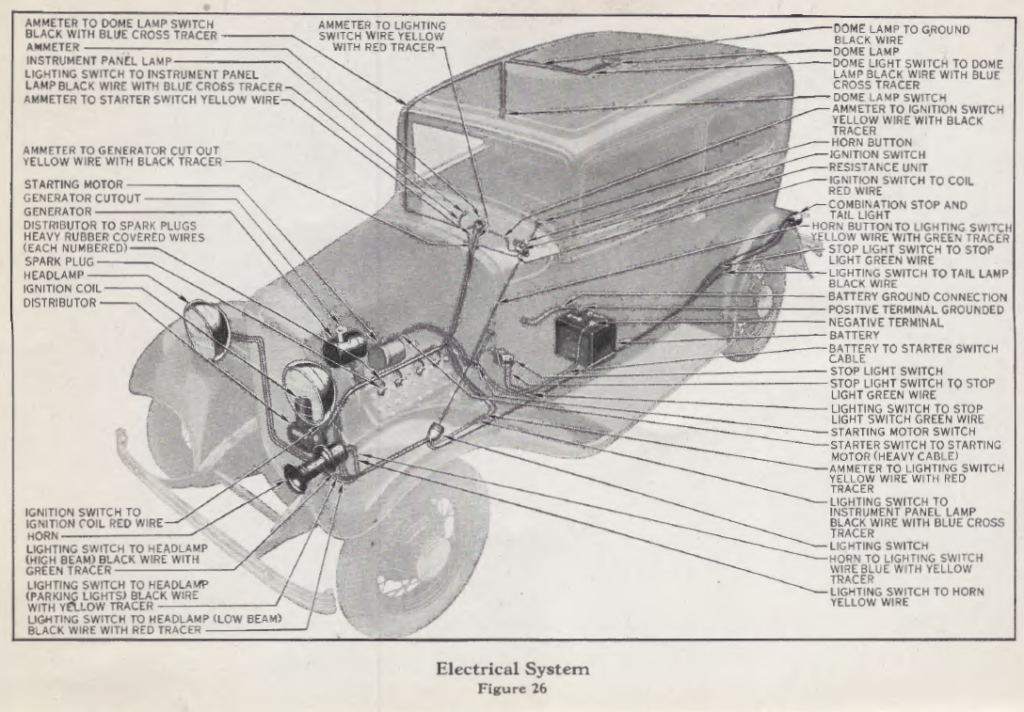
Loose or corroded battery connections increase the line resistance, raising the voltage of the generator often beyond the capacity of the light bulbs, causing them to burn out, and causing the breaker points to burn and pit.
Keep the battery filling plugs and connections tight, and the top of the battery clean. Wiping the battery with a rag moistened with ammonia will counteract the effect of any of the solution which may be on the outside of the battery. A coating of vaseline will protect the terminals from corrosion. It is of vital importance that the battery is firmly secured in its supporting brackets at all times. If clamps arc loose, the battery will shift about in the compartment, resulting in loose connections, broken cells and other trouble. When repairs arc necessary, or if the car is to be laid up for the winter, take the battery to a Ford dealer for proper attention and storage. Do not entrust your battery to inexperienced or unskilled hands.
The Generator
The generator is mounted above and to the front of the engine. The charging rate must be adjusted to suit the individual electrical requirements of each owner. For example, the owner who takes long daylight trips should adjust the charging considerably lower than the owner who makes numerous stops or uses his lights continually.
The ideal charging rate is the lowest rate with which full battery charge is maintained. Insist upon your Ford dealer properly adjusting this.
Increasing or Decreasing Generator Charging Rate
To increase or decrease the generator charging rate, remove generator cover and shift the third brush. To increase the charging rate, shift the third brush in the direction of rotation; to reduce the rate, shift the brush in the opposite direction. The output of the generator is indicated by the ammeter located on the instrument panel. For average driving the charging rate should not exceed 10 amperes.
The Starting Motor
The starting motor is mounted on the right side o the engine. It requires no attention beyond seeing that the cable connections are clean and tight.
Spark Plugs
There is nothing to be gained by experimenting with different makes of spark plugs. The spark plugs with which Ford
engines are fitted when they leave the factory are best adapted to the requirements of the Ford engine. The gap between the points should be .025 inch.
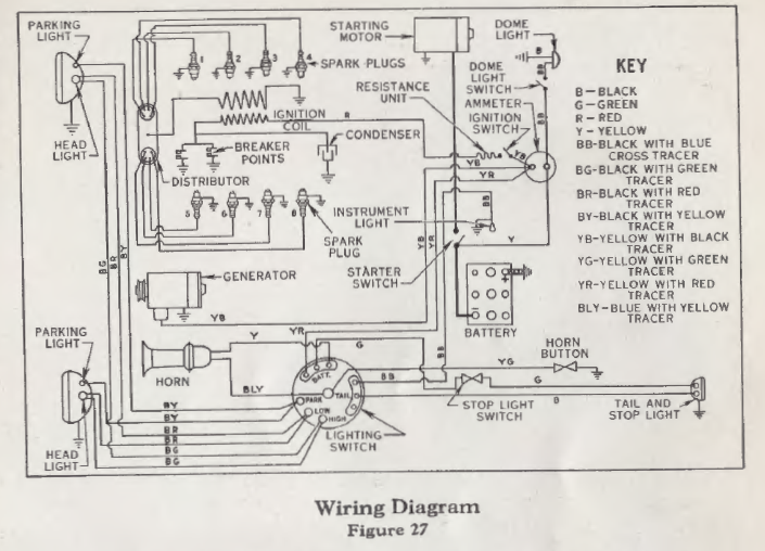
Engine Ignition
The current for igniting the gas mixture in the cylinders is provided by the storage battery. The ignition coil transforms the low tension current to a high tension current of sufficient voltage to bridge the gap between the points of the spark plugs. The circuit breaker points interrupt the flow of low tension current at regular intervals, while the distributor rotor distributes the high tension current to each spark plug in proper firing order.
Adjustment
The highly efficient ignition system on the Ford 8-cylinder cars should be adjusted only by Ford factory trained mechanics. No other one thing affects the operation of the car as vitally as incorrectly adjusted ignition which reflects
in poor performance, high fuel consumption and overheating of engine.
Trouble
However, should trouble be experienced, which by the process of elimination appears to be the result
of faulty ignition, if an authorized Ford dealer’s service is not available, the following procedure will assist in correcting it:
(1) Disconnect the red wire from the coil.
(2) Turn ignition switch to “ON” position.
(3) Touch disconnected wire to cylinder. If spark does not occur, using Figs.
26 and 27 as a guide, check each wire and connection, back
through the battery to the battery ground for a break in the
circuit.
(4) If spark occurs when the ignition switch to coil wire is grounded to the cylinder, remove the distributor side covers and examine the breaker points (see Fig. 29). If the points are worn, pitted, burned or incorrectly spaced, dress them smooth with an oil stone or, if an oil stone is not available, a file may be used. Adjust the gap to .012 inch with the fiber breaker arm on the high point of the cam. (Badly burned breaker points are usually an indication of a poor battery connection.) (Five thicknesses of newspaper is approximately .012 inch.) As soon as possible, allow an authorized Ford dealer to check your adjustment.
(5) Check the gap between the spark plug points. Clean the plugs and adjust to .025 inch.
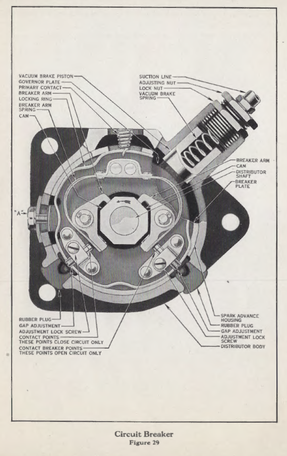
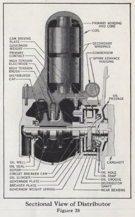
Distributor and Circuit Breaker
The distributor used on the Ford V-8 is located at the front of the engine and is driven direct by the camshaft, thus eliminating many parts. The spark timing is automatically retarded by the centrifugal governor weight springs for starting. By means of this centrifugal governor, the spark is automatically advanced at increased engine speeds in direct proportion to the speed. The spark timing is automatically retarded by the vacuum brake under load in direct proportion to the load.
Vacuum Brake
The vacuum brake consists of a plunger or piston which is held against the braking surface of the governor plate by a spring of adjustable tension. As the rapidity of combustion is dependent on the degree of compression, the need of a retarded spark for quick acceleration or power is not dependent entirely
on engine speed.
Lights
Operation of the Lights
The lighting system is operated by a switch handle, located at the top of the steering wheel. When the lighting switch handle is pointed straight clown, the lights are” off.” Turning handle first position to right from the “off” position gives a downward tilting beam for city driving. Turning handle to second position to right provides a beam which gives exceptionally brilliant road illumination for country driving. Turning the handle all the way to the left, turns on the parking lights.
Replacing the Bulbs
When replacing burned out bulbs, make certain that you get genuine Ford bulbs. Genuine Ford bulbs have the name “FORD” marked on the base. They insure your headlights meeting the lighting requirements of the various states.
Headlight Requirements
When the car is delivered, the headlamps are properly focused and aligned, and will pass the lighting requirements of all states.
The focusing of the lights is a permanently built in feature of the Ford headlights, requiring no attention. The focus will remain fixed as long as accurately built bulbs are used.
Should the lamps get out of alignment, they should immediately be realigned. Ford dealers are equipped for this service.
Aligning Headlamps
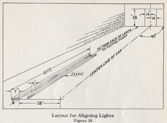
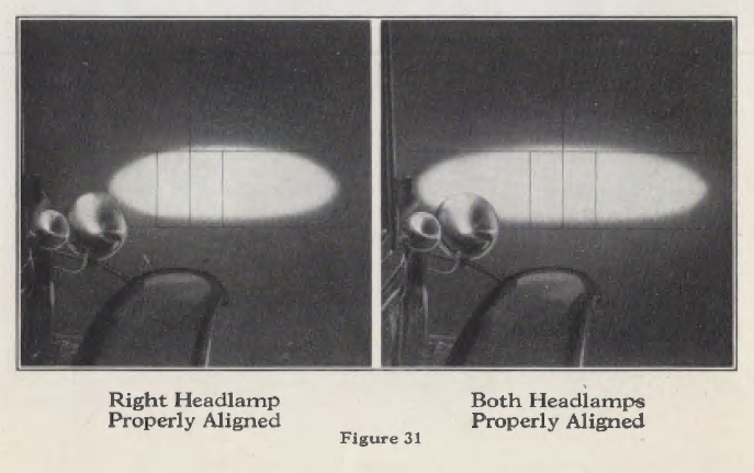
Align headlamps with empty car standing on a level surface in front of a white wall or screen, 25 feet from front of headlamps. This wall must be in semi-darkness or sufficiently shielded from direct light so that the light spots from the headlamps can be clearly seen. The wall must be marked off with black lines, as shown on Fig. 31. Details for making the layout are shown in Fig. 30.
Headlamps are aligned by moving lamps after nut at bottom of bracket has been slightly loosened. advise you on request if local requirements necessitate a different adjustment. The tops of the bright spots on the 25-foot wall arc to be set at a line 38 inches above level of surface on which car stands (see Fig. 30). 1Yith tops of bright spots thus set for empty car, the headlamps comply, under all conditions of loading, with the requirements of nearly all states. Your local Ford dealer will advise you on request if local requirements necessitate a different adjustment.
The beam of light from each headlamp is to extend straight forward, that is, the centers of the elliptical spots of light must be 28 inches apart.
Proper alignment of headlamps is readily checked by means of a horizontal line on the wall in front of the car, 38 inches above the level surface on which the car stands, and two vertical lines 28 inches apart, each one 14 inches from center line of car. Proper alignment of car relative to marks on the wall may be readily provided by use of wheel guide blocks for one side of the car, as shown in Fig. 30. If it is impossible to tic up the floor space required by these blocks, marks painted on the floor may be used to show where one set of wheels should track and where the car should be stopped.
Automatic Ride Control
Ford hydraulic double-acting shock absorbers operate entirely on the principle of hydraulic resistance. Shock absorber fluid is forced from one chamber to another by the movement of the lever arm. The working chamber is automatically kept full by the shock absorber fluid in the reservoir.
The shock absorbers are provided with thermostatic valves which automatically open or close to maintain the resistance required for the necessary snubbing action of the shock absorber. Automatically changing the size of the passage through which the fluid must pass to compensate for the change in the viscosity of the fluid under various temperatures.
In addition to the thermostatic control, another automatic feature has been incorporated in the Ford shock absorber by means of which the shock absorbers instantly and automatically adjust themselves to the condition of the road. This is accomplished by a simple but ingenious valve arrangement which works entirely independent of the thermostatic valve.
When the car is operated over pavements, the action of the shock absorbers is slight, and little resistance is required. However, should the car pass over a bad bump in the road, the fluid would be forced through the valve rapidly. The impact of this rapidly traveling fluid automatically adjusts the valve, thus increasing the resistance when, and to the degree, required, effectively adjusting the shock absorbers to instantly meet the road conditions encountered. As soon as the rapid movement of the fluid is stopped, the valve again automatically opens until such time as increased ·resistance is again required. By this arrangement the driver is relieved of all worry as to what the correct adjustment should be for any particular road condition.
Care
The only care the shock absorbers require is replenishing the shock absorber fluid in the reservoir. The filler plug in the reservoir should be removed each fall and spring or at intervals of 5,000 miles, whichever occurs first, and the reservoir filled with Ford shock absorber fluid. Ford dealers are equipped to render this service, as well as make such repairs as may in time be required.
Grease or oil should never be added to the shock absorber.
The Body
The Proper Way to Wash the Car
Always use cold or lukewarm water-never hot water. If a hose is used, don’t turn the water on at full force as this drives the dirt into the finish. After the surplus dirt has been washed off, take a sponge and clean the body and running gear with a solution of water and linseed oil soap. Rinse off with cold water; then rub and polish the body with a damp chamois skin. A body polish of good quality may be used to add luster to the car. The use of Lincoln body polish is recommended. This polish, developed for use on Lincoln cars, is available through Ford dealers. Grease on the running gear may be removed with a cloth or sponge moistened with gasoline. The bright parts should be polished with a good nickel polish. An excellent nickel polish can also be purchased from any Ford dealer.
Should the body or other pyroxylin finished parts of the car become spattered with tar or other substances used on roads, the spots can be removed with a solution of ½ gasoline and ½ engine oil.
Dip a soft cloth into the mixture and, using one finger, rub the spot gently until it has been removed. The rubbed spot should then be washed off with clear water.
Care of the Top
When putting down the top, be careful in folding to see that the fabric is not pinched between the bows, as they will chafe a hole through the top very quickly. Applying Ford top dressing will greatly improve the appearance of an old top on either an open or closed car. However, top dressing should never be applied to the top when new or before the top material starts to check.
Storing Car
Drain the water from the radiator, then put in about a quart of anti-freeze solution to prevent freezing of any water
that may possibly remain. Draw off all gasoline. Drain the old oil from the oil pan. Refill the oil pan with one gallon of fresh oil and run the engine enough to cover the different parts with oil. Remove the tires and store them. Wash the car and if possible cover the body with a sheet of muslin to protect the finish.
The battery should be recharged once each month.