
1932-1936 Ford Ignition & Electrical
Distributor Test Specification
All 1932 Models: Distributor type 18; Contact Spring Tension-19 to 22 ounces; Manual Advance Adjustment-
5°; Maximum Automatic Advance-22° at 1500 r.p.m. of the distributor.
All 1933 Models: Distributor type 40A; Contact Spring Tension-22 to 28 ounces; Manual Advance AdJustment-10°; Maximum Automatic Advance-22° at 1500 r.p.m. of the distributor.
All 1934, 1935 and Early 1936 Models: Distributor type 40B; Contact Spring Tension-22 to 28 ounces; Manual Advance AdJustment-10°; Maximum Automatic Advance-16° at 1475 r.p.m. of the distributor.
Late 1936 Models: Distributor type 68; Contact Spring Tension-20 to 24 Ounces; Manual Advance Adjustment-
10°; Full Automatic Advance-20° at 950 r.p.m. of the distributor.
Note: Full automatic advance specifications given above for all models are taken with the vacuum brakes inoperative.
Distributor & Cylinder Head Combinations
Engine performance will be affected if the correct type of distributor is not installed with the cylinder head for which it was designed. When a distributor is replaced with a new unit or if the cylinder head of the engine ls changed, be sure that the correct distributor for that cylinder head is installed.
A type B distributor, which is not marked, should be used with an iron cylinder head of 5.5 to 1 compression ratio and either single or dual carburetors.
A type “40A” distributor should be used with an aluminum cylinder head of a 6.3 to 1 compression ratio and single carburetors. The type of distributor can be identified by the mark “40A” on the end of the distributor shaft or on the governor weights. The mark on the governor weights can be seen through the vacuum brake opening in the side of the housing after the vacuum brake parts have been removed.
A type “40B” distributor should be used with an aluminum cylinder head of a 6.3 to 1 compression ratio and dual carburetors. The type of distributor can be identified by the mark “34” or “40B”, on the end of the distributor shaft or on the governor weights.
A type “68” distributor has been used in partial production in 1936 models with steel pistons and the new type cylinder head. These distributors have the new flat top coil and new type breaker plate which has the cam adjustment shown in Fig. 28.
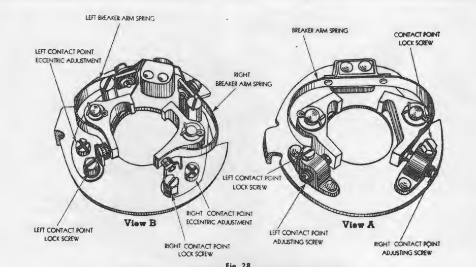
View B -Late type breaker plate showing eccentric adjustment for spacing contact points.
Vacuum Brakes
How to Adjust the Vacuum Brake to Stop Engine Ping: Engine ping on a Ford V-8 is generally caused by an improper adjustment of the vacuum brake on the distributor.
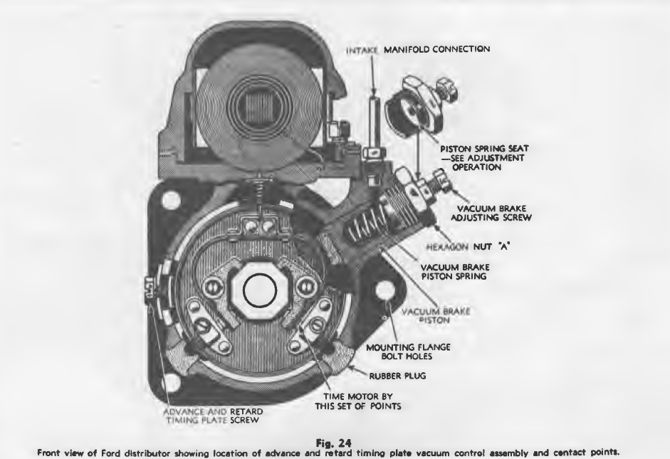
This device consists of a spring loaded piston, Fig. 24 which operates against the governor plates to retard the spark at the proper time in relation to the throttle opening. On sudden acceleration, the compression in the cylinders is abruptly raised which will cause the engine to ping unless the spark is retarded to compensate for the change in the speed of combustion due to the increased compression.
The tension of the piston spring can be regulated by the vacuum brake adjusting screw and all adjustments should be made on the road. To make this adjustment, proceed as follows:
1) Remove hexagon nut A,. Fig. 24 and take out the piston spring and piston. Examine the1e parts closely to see that the platen does not bind. Apply II few drops of light engine oil to the platen.
2) Reinstall the piston, spring and nut. Back the vacuum brake adjusting screw out to the limit.of Its adjustment being very careful not to force It to the point where the piston spring seat la forced off the end of the screw. If this should occur, 11 proper vacuum brake adjustment cannot be obtained with my amount of experimenting.
3) Accelerate car with wide open throttle. Engine should ping.
4) Screw In the vacuum brake adjusting screw slightly and accelerate car again. Repeat this operation until ping Just disappears.
When making these teats II good grade of gasoline should be used and the engine should be properly timed.
How to Remove and Dismantle Distributor
Note: It is not necessary to remove the radiator to take off the ignition distributor.
1) Disconnect the intake manifold connection and remove the distributor cap and cover. The Intake manifold connection is shown in Fig. 24.
2) Take out the three mounting flange bolls and lift the distributor assembly off the engine.
3) Remove the vacuum brake assembly by unscrewing the hexagon nut A. Fig. 24.
Caution: Be careful not the back off the vacuum brake adjusting screw too far otherwise there Is danger of forcing the piston spring seat off the end of the adjusting 11Cl’8W thus making It impossible to obtain a correct vacuum brake adjustment
4) Remove the two rubber plugs over the contact point screws.
5) Take out the three screws holding the Ignition coll In place and remove.
6) Take out the advance and retard timing plate screws and the whole Inside mechanism of the Ignition distributor assembly can be
pushed out of the housing.
7) To reassemble the distributor, reverse the above operations.
Contact Points
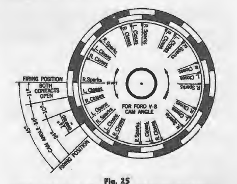
portion indicates the intervals the points are closed while the light portion indicates the intervals of opening.
Principle of Operation
The two sets of contact points in the Ford V-8 distributor operate on an overlap system. The right-hand contacts, looking at the front of the breaker plate, Fig. 24, break the circuit and do the firing. The left-hand contacts close the circuit. When one set of contacts only ls allowed to operate, the circuit ls open through 21 ° and closed through 24 °. With both sets of contacts in operation, the circuit remains open for a period of 11 ° and closed for a period of 34 °. This cycle occurs 8 times per revolution of the cam. The number of degrees through which both sets of contacts remain closed at the same time is termed “the overlap”. A complete cycle of opening and closing of both sets of contacts from one position of firing to the next can be traced on the chart shown in Fig. 25. Starting from the firing position (opening point) of the right set of contacts
(marked “R. Sparks” and “Start” on the diagram) both sets of contacts remain open for a period of 11 ° at which time the left set of contacts close-the right contacts remaining open for another 10°. The right contacts then close and both sets remain closed for a period of 14° at which time the left set opens. The next firing position or opening point for the right set of contacts will be reached 10° after the left set opens. This completes the cycle. From this chart it will be seen that the arc or angle of rotation from the point at which the circuit is closed by the left set of contacts is exactly 34°. This angle is known as the cam angle and if the contact points are to function properly, they must be adjusted to open and close at intervals exactly as indicated on this chart.
How to Adjust Contact Points
Contact Point Clearance:
– 1932 models-.012″ to .014″, cam angle 34°;
– 1934, 1935 and early 1936 models-.012″ to.014″, cam angle 34°;
– Late 1936 models with new type distributor-.014″ to .016″, cam angle 34°.
Cam Angle Adjustment: When new contacts are installed in the Ford V-8 distributor, it is necessary to accurately adjust the cam angle to obtain maximum motor performance and satisfactory contact life. If the steps contained in the following procedure are carefully followed, the contacts will function exactly right and the proper 34 ° cam angle will be obtained.
1) Take the distributor off the car and dismantle it.
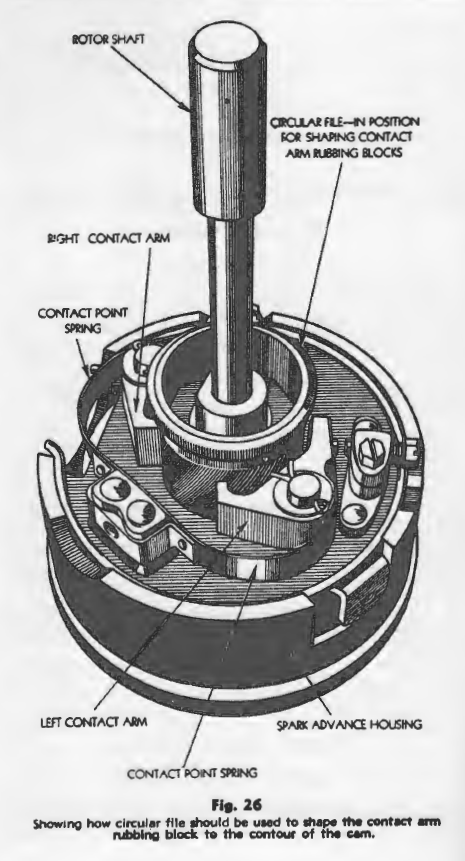
2) Install new breaker plate and shape the contact arm rubbing blocks to the distributor cam with a circular file. The procedure for this operation is shown in Fig. 26.
Note: Do not file off more material than is absolutely necessary to shape the rubbing block11 to the contour of the distributor cams.
3) Test the tension of the contact arm 1prlng1 by attaching the hook of the spring tension gauge to the tip of the contact arm. Accurately adjust the contact spring tension to the specification given under “Distributor Test Specification.”
4) Lubricate the governor weights 10 that they work freely before placing this unit in the housing. Bear brand cam grease Is suitable for this purpose.
5) Assemble the distributor, mount the Ignition coll In postilion, tighten the timing screw and install the vacuum control Caution: Care should be exercised when mounting the ignition coll to tighten the mounting screws evenly, otherwise there may be danger of cracking the bakellte coll case.
6) Mount the distributor in a vise as shown In Fig. 27 and Install the cam angle disc In position on the end of the distributor drive shaft.
7) Mount the cam angle needle Indicator to the distributor housing flange and adjust the point of the needle to a position l / 64″ over the edge of the com angle disc.
8) Connect. the test light In series with the coll terminal and battery and ground the other side of the battery to the distributor housing.
9) insulate the left set of contacts by placing a piece of clean cardboard between the two tungsten points. The test light should now light up when the right-hand contacts are closed.
10) Tum the distributor rotor shaft slowly In the direction Indicated by the arrows etched In the cam angle disc and note the exact position at which the right-hand set of contacts opens (test light goes out). Hold the distributor shaft rigidly in the exact position and rotate the cam angle disc on !ta mounting, In a position opposite to the rotation of the distributor shaft until the calibrated mark at the word “Start” on the disc Is directly under the needle. This is the position of “R. Sparks” on the disc. Tighten the disc securely to its mounting in this position.
11) Rotate the distributor shaft through one complete revolution ID the direction of the arrows etched on the disc:, to make sure that the right-hand set of contacts opens (test light goes out) at the exact Instant the mark “R. Sparks” registers with the indicator needle.
12) Adjust the spacing of the right-hand Mt of contacts until they, remain open through the angle of rotation between the mark “R. Sparks” and “R. Closes.” Changing the spacing of the contact points changes the position of opening with relation to the rotation of the distributor abaft: therefore, It will be necessary to readjust the position of the cam angle disc on its mounting each time the contact spacing Is changed. When this adjustment Is correctly and accurately made, the right-hand set of contacts will open and close at a cam angle of exactly 24°.
Caution The positions of the cam angle disc and indicator needle must not be altered from that established for the right-hand set of contacts while adjusting the position of closing for the left-hand set of contacts.
13) Remove the Insulation from between the right-hand set of contacts and adjust the spacing of the left-hand set of contacts so that they close w.hen the mark ”L Closes” ill directly under the indicator needle. This adjustment when correctly and accurately made will increase the cam angle to a total of 34°.
14) Turn the distributor shaft slowly through one complete revolution and observe the opening and closing points of both set of contacts. If not within the tolerance Indicated b1• the broad portion of the calibrated marks on the cam angle disc for the entire rotation of the distributor shaft, Inspect the distributor for bent or worn rotor shaft.
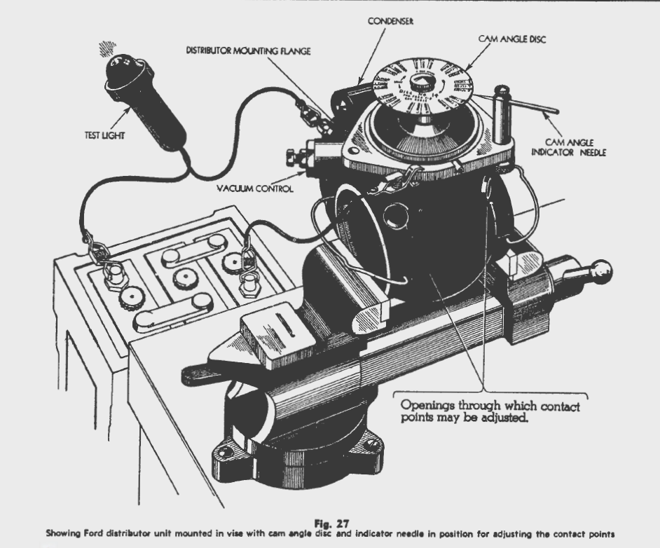
faulty cam or worn bushings. All faulty or worn parts should be replaced and the opening and closing of the contact points held within the tolerance limits Indicated, otherwise engine performance will be effected.
15) Finally, grease the cam with a good grade of cam grease. Use “Bear Brand No. GR-1” which is especially compounded for this purpose.
16) Mount the distributor on the car and time to the engine.
Breaker Plates
Early Type Breaker Plates: The early type breaker plate shown in View A, Fig. 28, was used from 1932 to 1936. The contact point spacing for this· type plate can be changed by loosening the contact point lock screws and turning the contact screws with a screwdriver. A
single breaker spring is used for both contact arms.
Late Type Breaker Plates: The late type breaker plate shown in View B, Fig. 28 went into production in 1936. The operation of spacing the contact points for this type plate is different from that for the early type plates.
To change the contact point spacing, loosen the contact point lock screw and tum the eccentric adjustment.Separate breaker springs are provided for each contact arm.
Note: The late type breaker plate is not interchangeable with the early type plate.
Ignition Timing
Engine Firing Order: The firing order of all Ford V-8 engines is 1-5-4-8-6-3-7-2. The cylinders are numbered in rotation as shown in Fig. 5.
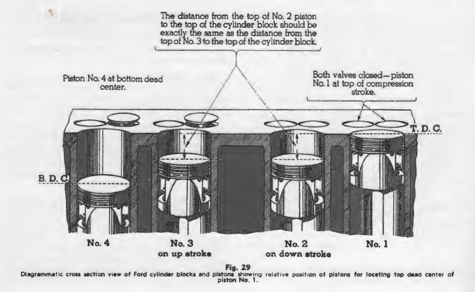
How to Locate No. 1 Piston at Top Dead Center: To locate piston No. l at top dead center of the compression stroke, crank the engine .until No. 1 piston is coming up on compression. No. 2 will be going down and No. 3 will be coming up as shown in Fig. 29. Continue cranking the engine until the top of · No. 2 piston is exactly the same distance from the top of the cylinder block as No. 3 piston. With the tops of No; 2 and No. 3 pistons in a plane exactly the same distance from the top of the block fol’. both pistons, pi$ton No. 1 will be at top dead center of its compression stroke and piston No. 4 will be at bottom dead center.
How to,Time the Distributor to the Engine:: If a dynamo-meter or tachometer is used to time the ignition, a load should be placed on the engine and the timing screw moved to obtain ma%i.mum power. To time the ignition distributor to the engine for .all passenger car and truck models, crank No. l piston (front cylinder, right bank) to top dead center of the compression stroke (see Fig. 29). Loosen the advance and retard timing plate screw, Fig. 24 and slide the timing plate down to the lower end of the slot. Turn the ignition switch on and
slide the timing plate up slowly until the spark occurs.
Note the position of the timing plate with reference to the center line on the distributor body and the graduation marks on the plate and move the timing plate up just one more graduation. If this adjustment has been correctly made, the spark will occur 4 ° before top dead center which is the correct firing position. Tighten the timing plate screw in this position.
Distributor Failures
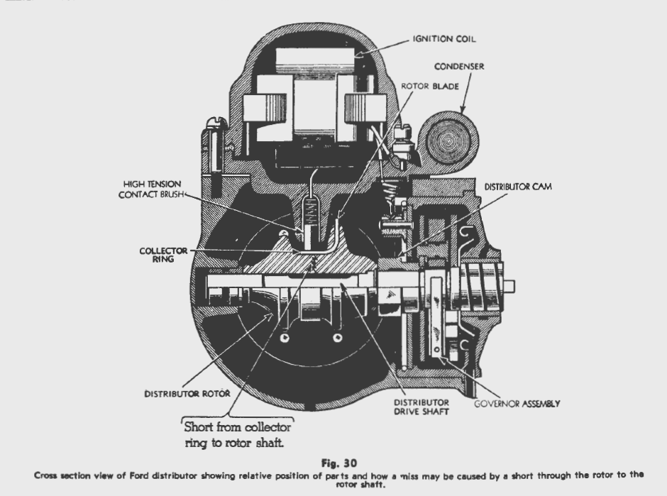
How to Correct Miss Caused by Shorted Rotors:
There is considerable difference between the trouble caused by a broken down rotor and a shorted cap. The rotor may break down at either of two points; namely, a break through the core of the rotor from the collector ring to the distributor drive shaft, Fig. 30 or a carbon path may form on the surface of the rotor to the rotor
blade, Fig. 33. If the short occurs from the collector ring to the drive shaft, all eight cylinders will be effected and
the car may perform very much as though the ignition timing had slipped; however, if the short is bad, it will not be possible to get the car started.
If the short is in the nature of a carbon path along the edge of the rotor to the rotor blade, usually one bank of cylinders only will be affected and the engine will run rough. The rough running condition is caused by early
firing of the cylinders affected.
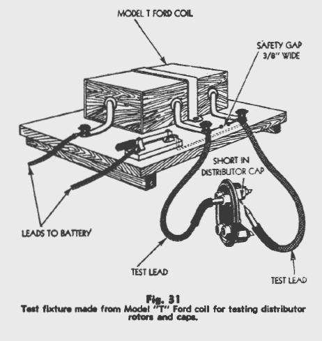
To test the rotor, rig up a Model “T” ignition coil as shown in fig. 31. Be sure to equip this test unit with a safety gap ¾H wide as shown. The point of the safety gap can be made by placing a drop of solder 1/a” in diameter on the end of each wire forming the gap.
Next, make a test fixture to hold the rotor as shown in fig. 32. To make this fixture, obtain a piece of flat cold rolled steel for a metal base. Drill and,tap a hole in the center to accommodate a section of 5/16″ cold rolled steel rod. Screw the rod into the center of the metal plate. On one end of the plate mount a binding post as shown.
To test the rotor for a short from the collector ring to the core, place the rotor over the 5/16″ rod and hold the test wire against the rotor blade. When making this test, the core of the rotor should not touch the 5/16″ rod at any point. If a spark occurs through the rotor’ to the rod, the rotor should be replaced. The duration of this test should not exceed 30 seconds. This test should be made with the metal base resting on a rubber mat thus insulating it from the bench.
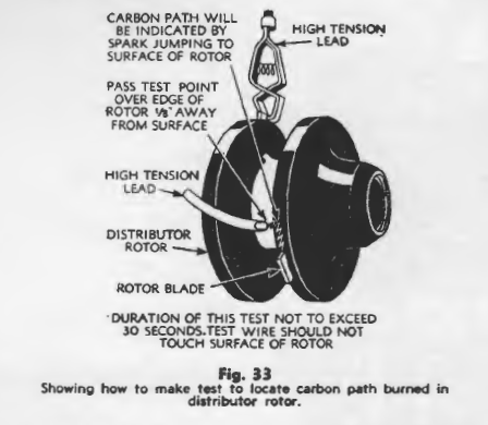
To test for a carbon path along the surface of the rotor to the rotor blade, proceed as illustrated in Fig. 33. Pass the high tension test wire over the edge of the rotor ¼” away from the surface. If a carbon path is present, the ::park will jump to the surface of the rotor and pass along it to the rotor blade. If a carbon path exists, the rotor should be replaced. The duration of this test should not exceed 30 seconds.
How to Correct Miss Caused by Shorted Distributor Cap: If the distributor cap is broken down or shorted out, the engine will generally miss on one or two cylinders. The trouble may sound like a shorted spark plug wire or a spark plug failure.
To test a distributor cap, the unit should be removed from the car; however, a preliminary test should be made first. If the miss sounds like distributor cap trouble, start the motor and take off each spark plug wire in rotation. With the plug wire removed, a distinct snap will be heard if the cap is broken down.
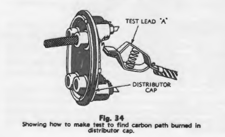
To test the distributor cap off the car, use the Model “T” Ford coil shown in Fig. 31. Place one lead of the coil test unit in the cap and pass the other lead around the base of the cap as illustrated in Fig. 34. If a short or carbon path exists, the spark will Jump as shown. All four contacts should be tested in the same manner. The test lead “A” should be held about ¼” away from the surface of the cap and the duration of the test should not exceed 30 seconds.
Spark Plugs
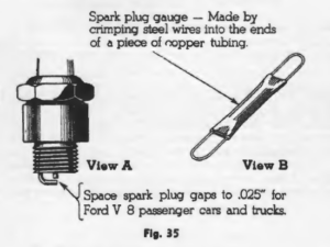
Spark Plug Gaps: The spark plug gaps for Ford V-8 engines should be spaced te .025″. The most accurate adjustment can be made if the gap measurements are taken with a wire gauge made up as shown in
View B, Fig. 35.
Caution: Be sure to select spark plugs with the long threaded section on the petticoat for use in aluminum cylinder heads. If this precaution is not taken and spark plugs with short threaded sections are used, there may be danger of stripping the threads in the cylinder head.
Fuse Capacities and Location
All Models from 1932 to 1936 Inclusive: One 20 amp. fuse is used for regular equipment or one 25 amp. fuse for radio equipment mounted in a fuse block located back of the instrument panel under the cowl.
Starting Motor Bench Test Specifications
All Ford V-8 Models from 1932 to 1936 Inclusive: Starting motor No. 18-11002; free running speed 2700 r.p.m. with current draw of 50 amperes at 6.0 volts; lock load stalled–current draw 465 amperes at 3.6 volts; normal cranking speed 1070 r.p.m. with current draw of 50 amperes at 6.0 volts.
Standard Equipment Generators
Bench Test Specifications
Caution: The following generator maximum rate capacities show the output that the generator is capable of
delivering and does not necessarily represent the rate at which the generator should be set on the car. Regulate
the output to suit the owner’s requirements, and the battery capacity.
All 1932, 1933 and early 1934 Models: Generator No. 10000A conventional third brush control; maximum
rate capacity–cold 12 amperes at 7 .0 volts at 1600 r.p.m.-hot 10.7 amperes at 6.9 volts at 1600 r.p.m.; brush spring tension for all brushes, 18 oz. All 1934 (late model A), 1935 and 1938 Model A: Generator No. l 0000B, conventional third brush control with two rate voltage control regulator when’ used in radio equipped cars and plain cutout when used as regular equipment; maximum rate capacity with two rate regulator-cold 18 amperes at 7.1 volts at 1500 r.p.m.-hot 16 amperes at 6.9 volts at 1500 r.p.m.; maximum rate capacity with plain tYP9 cutout-cold 12 amperes at 7.0 volts at 1500 r.p.m.-hot 10.5 amperes at 6.9 volts at 1500 r.p.m.; brush spring tension for all brushes, 18 oz.
How to Adjust the Generator Charging Rate
The current output for all standard equipment generators is regulated by moving the third brush. To increase the charging rate, move the brush in the direction of rotation; to decrease it, move the brush against armature rotation.
If the generator is regulated while mounted on the car, a test ammeter should be connected into the charging circuit at the generator to get an accurate reading. Note: The “F” terminal of generators equipped with a two rate voltage regulator should be grounded to the generator frame while regulating the charging rate.
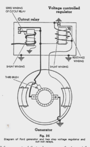
Principle of Operation of the Two Rate Regulators: A diagram of the two rate regulator and generator circuit is shown in Fig. 36. When the voltage in the battery charging circuit reaches 8.5 volts the regulator points open and cut a resistance unit into the generator field circuit. This resistance reduces the total generator output to from 3 to 4 amperes. The regulator points remain open, maintaining the low charging rate until the engine is either stopped or slowed down below generator charging speed at which time the cutout relay points open and break the generator charging circuit. This permits the regulator points to close and shunt out the resistance unit.
The regulator points will now remain closed and the generator will charge at the higher rate until the voltage of the charging circuit again reaches 8.5 volts at which time the regulator points will again open, cutting the field resistance into the circuit.
Caution: High resistance at any point in the generator charging circuit may raise the charging voltage and cause the voltage regulator to cut in the field resistance. If the generator fails to charge correctly, inspect the
charging circuit for loose terminals, broken or corroded connections, or high resistance in the battery. All connections
should be clean and tight and the battery should be kept in good condition.