
1932-1936 Engine Manual
Engine

Valve Timing
All Ford V-8 Engine from 1932 to 1936 Inclusive: To check the valve timing for all Ford V-8 engines from 1932 to 1936 inclusive use the following procedure:
1) Remove the starting motor.
2) Crank the engine until piston No. 1 is on top dead center exhaust stroke. The complete procedure for locating piston No. 1 on top dead center for the compression stroke is given under ‘Ignition Timing”. The procedure for valve timing is the same except that No. 1 piston a hold be coming up on exhaust stroke.
3) Place a chalk mark on the flywheel rim and engine housing.
4) Back the flywheel turn counterclockwise until the Intake valve is closed and rotate it slowly again in a clockwise direction until the Intake valve just starts to open.
5) If the valves are timed correctly the Intake valve will open approximately three flywheel teeth before top dead center.
Timing Gear Marks
To correctly set the valve timing by the timing gear marks, the mark on the camshaft gear should line up with the mark on the crankshaft gear. The location of these marks on the timing gears is shown in Fiq. 1.
Valve Tappet Clearances
The valve tappet clearance should be adjusted to .0125″ for the low limit and .0135″ for the upper limit. Special gauges for taking these measurements can be
purchased from your jobber. If the clearance is found to be too close the end of the valve stem should be ground off until the correct clearance is obtained. if the clearance is found to be too great it may be reduced by either refacing the old valve or replacing it with a new one.
Valve stems must be ground absolutely square when adjusting the tappet clearance. If this precaution ls not taken, valve noises may develop. (See Fig. 6).
One of the chief contributing factors to poor motor performance and excessive oil consumption is sloppy valve guides. Whenever valve stems and guides have been found to be worn until the clearance between these parts is in excess of .004″, they should be replaced.
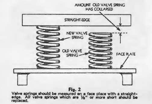
Valve Springs
Old valve spriD911 should be replaced when they have collapsed to a length ¼” (or more) less than the
length of a new spring. These measurements should be taken by placing the old spring on a face plate on end beside a new spring as shown in Fig. 2. The relative length of the springs can be determined with a straightedge as shown in the illustration. Valve springs that are not square and parallel on the ends should be discarded for new springs.
Correct Procedure for Grinding Valves
A mechanic who is not familiar with Ford V-8 repair procedure may lose a lot of time on a valve grinding Job if he does not follow the standard recommended practice for doing this work. Much time can be saved by knowing how to locate the camshaft so that the push rod for each valve rests exactly on the heel of its cam and how the valve assemblies should be removed, etc. These operations are given in the following paragraphs.
How to Dismantle the Engine for Valve Grinding Operation:
First, disconnect the fuel lines and loosen up the fuel pump. Remove the valley cover, carburetor, generator, etc., as a unit. The valve assemblies can now be removed.
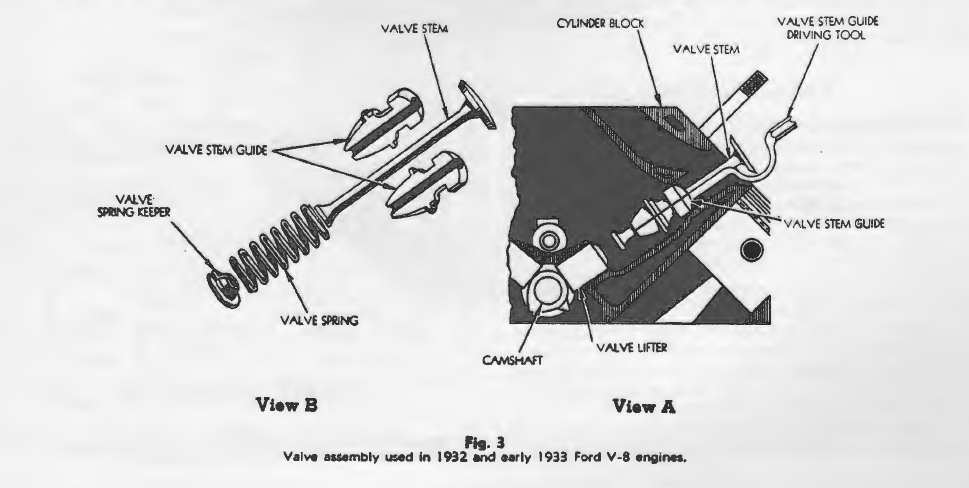
How to Remove the Valve Assemblies:
In all 1932 and early 1933 models, valve stem guides of the design shown in Fig. 3 were used. These guides had a flange or shoulder which would not permit the guide to be removed through the valve port. In order to remove this type of valve assembly it was necessary to lift the valve spring, remove the spring keeper and drive the valve stem guide down out of the block with a special driver designed for this purpose as shown in View A.
The valve guides used in all models from late 1933 to 1936 inclusive were of the design shown in Fig. 4. These guides were held in by a valve stem guide retainer as shown in View A. To remove the valve assemblies with this type valve guide, insert a special bar type lifter between the coils of the valve spring and pry the spring down clear of the retainer. After the retainer has been removed, the valve, valve guide and spring assembly can be pulled out through the valves port.
Caution:
There may be danger of breaking the flange off the lower end of the guide or damaging the valve stem if too much pressure is applied with the bar when the guide is stuck in the block. When this trouble if encountered, remove the spring keeper from the lower end of the valve stem and allow the spring to slide down. Lift the valve up and loosen the guide with the special valve guide driver illustrated in View A, Fig. 3.
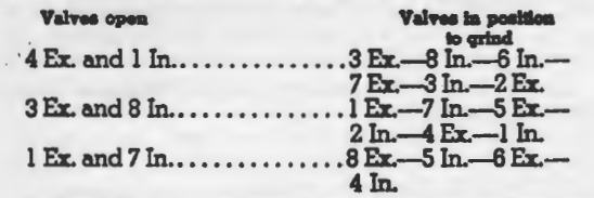
How to Locate Crankshaft
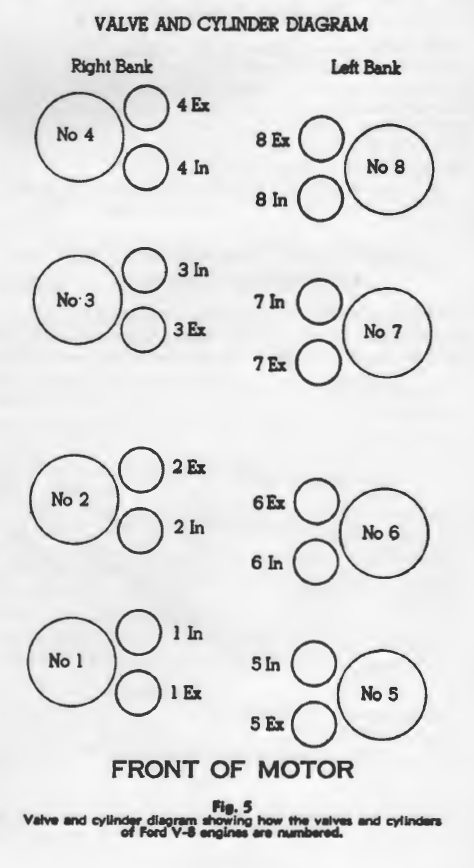
will correct position to Grind Valves: In order to do a satisfactory valve grinding Job on a Ford V-8, it is necessary to have the camshaft located so the valve push rod rests exactly on the heal of the cam for the valve which is to be ground. The proper location of the camshaft is determined by the open positions of certain combinations of valves. For example, if the engine 18 cranked until No. 4 exhaust and No. l intake are open, Noe. 3, 7 and 2 exhaust and 8, 6 and 3 intake valve a will be in position for grinding. The table below shows three positions of the camshaft for grinding all valves. Thia table can be quickly and easily interpreted by referrer to Fiq. 5 which 18 a diagram showing how the cylinders are numbered and the location of the valves for each cylinder.
It should be remembered that cylinders and valves are numbered beginning with the cylinder nearest the radiator of the right bank as No. 1. The cylinder nearest the radiator in the left bank of No. 5.
Valve Noises
Valve noise maybe originate from three sources in a Ford engine, The early model cars used a push rod with a small hole 1n the bottom u shown 1n View A, Fig. 6. After an extended period of service, very often the underside of these push rods wears to a rough. wavy surface around the hole. h the wear becomes excessive a noise will develop very similar to that produced by a broken piston or bad pin.
To correct the trouble, replace the old push rod with one of the new type.
A second cause of a knocking noise which may develop is caused by valve stems which have not been ground true. If the end of the stem has not been ground true, the bearing surface of the stem will be reduced to a point where the stem will bear on one edge only as shown in View B, Fiq. 6. When this happens, the narrow bearing surface of the stem will cut through the oil film. and cause a knocking noise. To correct this trouble, grind the end of the valve stem square 1n a Jig for this purpose. The third cause of a valve noise or knock may be traced to a valve guide retainer which has been installed 1n a cocked position. Extreme care should be exercised when installing valve guides and retainers to see that these parts are properly installed.

Cylinder Dead Gaskets
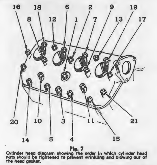
To prevent cylinder head gaskets blowing out after a valve grind fob, be sure to install the gasket with the side marked “front” to the front of the engine and the side with the large holes to the rear. Cylinder head nuts should be tightened 1n the’ order given in the diagram shown in Fig 7. First, run all the nuts down snug with a speed wrench. Next, tighten them fairly snug with a head nut wrench 1n the same order and finally go over them a third time drawing them down securely. If the same order of tightening 19 followed each time the nuts are tightened, danger of wrinkling the gasket or distorting the head will be avoided.
Timing Gears and Camshaft
Camshaft end play in all Ford V-8 motors is controllers by the timing gear cover plate shown in Fig. 8. This
plate bears against the hub of the camshaft and prevents end wise movement of the shalt. The camshaft ls
gear driven and is mounted on three bearings. The oil

pump, drive gear and fuel pump actuating cam are mounted on the rear end of the camshaft while the distributor assembly is driven by a slot in the front end of the shaft.
To remove the camshaft
… to replace the camshaft gear it will be necessary to take off the radiator, the valve valley cover, both cylinder heads, valves and push rod and take off the distributor and timing gear cover plate. The camshaft can then be pulled out from the front. The camshaft gear is pressed onto the camshaft hub. When a new gear is installed be sure the mark on the gear registers exactly with the line on the hub of the camshaft as shown in Fig. 1.
How to Remove the Oil Pan
All 1932 to 1934 Models Inclusive: It is a fairly simple operation to remove the oil ~ 1n these models. No
difficulty will be encountered if the work is done in the following order.
1) Lift the front end of the car off the fleet with a chain hoist attached to the bumper.
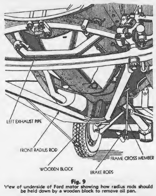
2) Remove the left exhaust pipe shown In Fig. 9.
3) Remove the radius rod ball cap and place a wooden block about 12 .. long between the radius rod ball and the frame cross member to hold the radius rods down out of the way.
4) Disconnected the front brake rods and let them hang down.
5) Disconnect starting motor cable. It will not be necessary to remove the starting motor to take the oil pan down.
6) Take out the 5/16″ oil pan cap screws along the sides of the oil pan and the four %” cap screws through the rear oil pan flange. Also remove the one 5/16″ cap screw from the top right hand side Just back of the starting motor. The oil pan can now be removed. Note: It may be necessary to loosen the fan pulley and slide It ahead
ll It Interferes with the pan.
All 1935 and 1936 Models inclusive:
A mechanic who is not familiar with Ford V-8 repair procedure may have considerable difficulty removing the oil pan on these models if he does not follow the standard recommended practice. Much time can be saved if the work is done by the following operations.
1) Drain the radiator, remove top radiator hoses and loosen clamp on lower hoses.
2) Disconnect front motor supports and remove generator 80 the fan blades will not puncture the radiator.
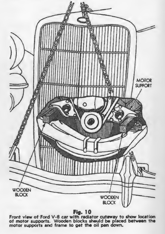
3) Jack up front end of motor as high as possible (approximately 2 1/3″) and block In this position by placing wooden blocks between the motor supports and the frame as shown in Fig. 10.
4) Lift the front end of the car off the floor with a chain hoist attached to the bumper,
5) Remove the left exhaust pipe shown in Fig. 9.
6) Remove the radius rod ball cap and place a wooden block about 12″ long between the radius red ball and the frame cross member to hold the radius rods down out of the way.
7) Disconnect the front brake rode and let them hang down.
8) Loosen the fan pulley and pill] it ahead far enough to clear the front end of the oil pan.
9) Disconnect the starting motor cable. It will not be necessary to remove the starting motor to take the oil pan down.
10) Take out all cap screws holding the oil pan In place. Do not overlook the 5/16″ cap screw which la removed from the top and is located just behind the starting motor.
11) Place the crankshaft In such a position that the counter weights of the front throw will be In the down position. This position of the crankshaft will allow the greatest amount of clearance between the oil pan and the crank.haft. The counterweights will be In the down position when No. 1 piston Is approximately I¼” from the top of the block with No. 5 approximately 2 3/4 from the top of the block. The oil pan can now be removed.
Caution: When a late type engine block assembly is to be installed in a 1932 or a 1933 model, the rear main bearing return pipe should be sawed off at least 1/2”. If this pipe is not cut off there may not be enough clearance between the end of the pipe and the oil pan to allow the oil from the bearing to return to the oil pan freely. A rear main bearing oil leak would develop as the result.
Pistons
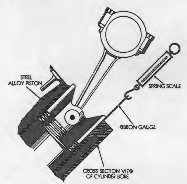
Steel alloy pistons may be fitted with a .003″ ribbon feeler gauge as shown in Fig. 11. The feeler gauge should be inserted between the piston skirt and the cylinder wall at right angles to the pin. The clearance will be correct when the feeler gauge can be pulled out by a pull of from 5 lbs. to 8 lbs.
Aluminum alloy pistons should be fitted to the cylinders with the aid of a telescope gauge and an outside micrometer as shown in Fig. 12. The pistons will be correctly fitted when the clearance at right angles to the pin is from .0015″ to .002″.
Oversized finished pistons can be purchased from your jobber in the following standard sizes: .01 0″, .020″, .030″ and .040″.
Pistons are removed from the top of the motor in all Ford V-8 engines. All connecting rods and caps are marked with the numbers of the cylinders from which they have been removed. Care should be exercised not to get the caps mixed up and the rod assemblies should be reinstalled in the cylinders from which they were removed. The numbers on the rods and caps are on the side away from the crankshaft.
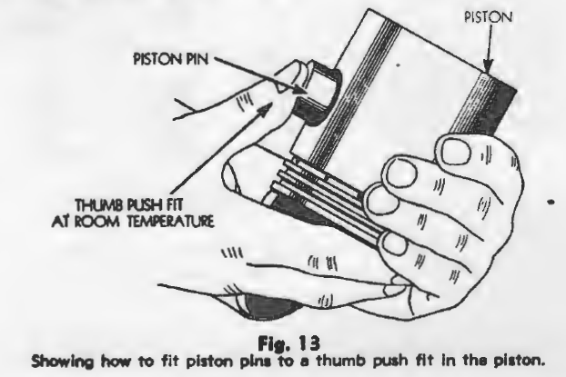
Piston Pins

Piston pins should be fitted to a thumb push fit in alloy pistons at 200°F. and a thumb push in the rod at room temperature. The pistons may be heated in boiling water if no special heating fixture is available.
The pins in steel alloy pistons and rods should be fitted to a thumb push fit at room temperature as shown in Fig. 13. The pin floats in the piston and in the rod for both steel and aluminum alloy pistons. It is held in by a lock ring in the center of the pin bushing for aluminum alloy pistons and by expansion plugs pressed into the recesses of the piston pin bore in the piston for steel alloy pistons.
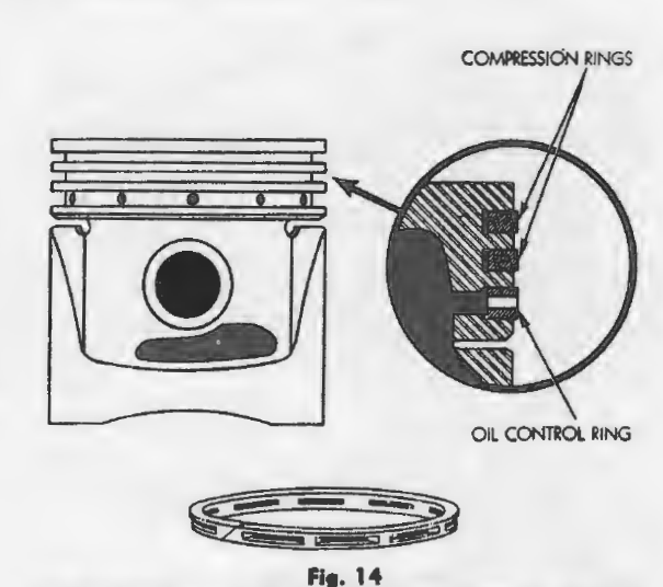
Piston Rings
Piston rings should fit free in the grooves with a side clearance not to exceed .0025″. All Ford V-8 engines from 1932 to 1936 inclusive have three ring grooves above the piston pin. Compression rings are used in the first two grooves and an oil ring is used in the third groove as shown in Fig. 14.
The piston ring gap clearance should be adjusted as follows: Top ring .010″ to .015″; center ring .009″ to .015″; oil control ring .005″ to .012″.
The piston ring gap clearance should be adjusted as follows: Top ring .010″ to .015″; center ring .009″ to
.015″; oil control ring .005″ to .012″.
The greatest taper In a worn cylinder is generally found in the top inch of the ring travel and parallel with
the crankshaft. When the pistons are removed for the purpose of installing a new set of rings, the ridge or ledge at the top of the ring travel must always be removed. A good ridge reamer should be used for this purpose and the tool should be set so that it will not cut down into the ring travel more than 1/32″. The shavings will not fall down into the crankcase if the ridge is reamed out before the pistons are removed. With the ridge and hard carbon deposits cut out of the top of the cylinder, the pistons can be removed easily and without damage to the rings or pistons.
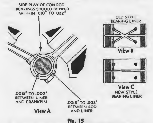
Connecting Rod Bearings
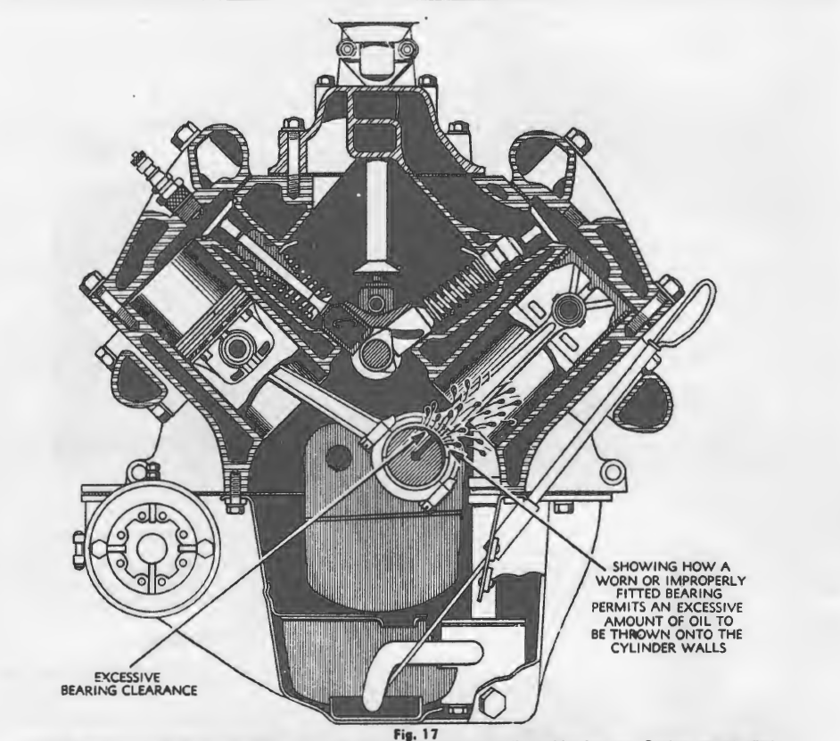
The connecting rod bearings are of the plain side by side type. The rod bears against a liner that floats between the rod and crank pin. These bearings are not adjustable and should be replaced if worn beyond the limits shown in View A, Fig. IS. If the bearings do not have the proper clearance, a condition will arise where
an excessive amount of oil will be thrown onto the
cylinder walls as shown in Fig. 17.
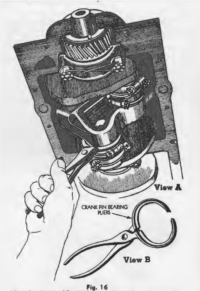
The amount of wear in the connecting rod bearings can be checked by placing a piece of shim metal .005″ thick by 1/:a” square between the rod cap and the liner. With the connecting rod cap drawn up tight, the .005 .. shim stock should create a stiff drag or lock the bearing on the shaft. The drag of the bearings should be tested with crank pin bearing pliers as shown in Fig. 16. If the liner is still fr8’l to tum, the clearance will be too great and the liners should be replaced.
Some Ford V-8 engines have been delivered with undersized crank pins. In these engines the under size is marked in the oil groove of each bearing half. Whenever old bearings are replaced with new ones be sure to note whether the bearings are under size to avoid installing standard sized bearings on an undersized crankshaft.
Old style bearing liners View B, Fig. 15 should be replaced with the new style shown in View A, whenever excessive wear warrants replacement.
Caution: Do not under any circumstances, attempt to adjust the connecting rod bearings by filing the caps or the bearing inserts.
Crankshaft
The crankshaft end thrust in all Ford V-8 engines is taken on the rear main bearing. The end play will be correct when it does not exceed the limits of .002H to .006″. If end-play becomes excessive it can be reduced by replacing the rear main bearing cap. The front crankshaft oil Mal fits around the hub of the fan drive pulley at the front end of the motor as shown in Fig. 8. Whenever the oil seal packing is replaced, it should be soaked in cylinder oil for at least 45 minutes before it is installed in the motor. If this precaution is not taken, the new packing may score the fan pulley hub and cause an oil leak: before enough oil works into the packing from the crankcase to lubricate it. If scoring does occur, both the fan pulley and oil seal should be replaced.
Main Bearings
The main bearings in all Ford V-8 engines from 1932 to 1936 are not adjustable. The bearings are integral with the crankcase and bearing caps and must be rebabbitted and reamed when wear becomes excessive. Do not attempt to file the bearing caps.
The amount of wear In each main bearing can be checked by bolting the cap up against a piece of .005″ shim metal, ½” wide by the length of the cap. With the bearing cap drawn up tight, the .005H shim stock should create a stiff drag or lock the bearing on the shaft. If the shaft turns free the wear is too great and the bearings should be replaced. The bearing clearance will be correct when it is within the limits of .001″ to .003″.
Fan Belt
The fan belt adjustment will be correct when the belt can be moved in and out a distance of approximately 1″ with the thumb and finger. The tension of the belt can be changed by moving the generator on its support. Be careful not to adjust the fan belt too tight because the excessive down pressure would wear out the generator bearing.
Water Pumps
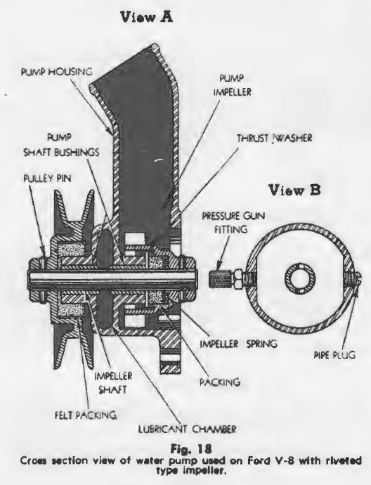
A water pump with a riveted type Impeller is shown in Fig. 18. To dismantle this pump, take it off the engine and drive the pump pulley pin out. The impeller and shaft assembly can then be pushed out at the rear. These water pumps should be lubricated with chassis lubricant only and not with a heavy grease. A heavy grease may have a tendency to congeal and harden in water and the pressure would push the spring and packing forward which would allow water to leak past the bushing.

A water pump with a detachable type Impeller is shown in Fig. 19. To dismantle this pump, take it off the engine, press the impeller spring in and unhook it from the recess in the pump housing. The spring and impeller can then be lifted out from the rear. To remove the pump shaft, unscrew the shaft retainer nut and draw the shaft and pulley assembly out from the front.

A heavy duty type water pump used in Ford V-8 trucks is shown in Fig. 20. These pumps are of the heavy duty type and are equipped with roller bearings. To dismantle this pump, take it off the engine. Press the impeller spring in and unhook it from the recess in the pump housing. The spring and impeller can then be lifted out from the rear. To remove the pump shaft and roller bearings, unscrew the shaft retainer nut and draw the shaft and pulley assembly out from the front. The roller bearing assemblies can then be slipped out.
Lubricate the roller bearing with chassis lubricant and fill the oil reservoir with an oil of the same S.A.E. number as that used in the engine crankcase. When replacing water pumps on V-8 engines, be sure that the new pumps are of equal capacity for each cylinder block.
Flywheel

When a new flywheel is installed in a 1932 engine be sure that the crankshaft flange has been chamfered to 5/64″ as shown in Fig. 21. The crankshaft flange will not accommodate the radius in the counter-bore of the flywheel if the edge of the flange has not been chamfered.
The runout of the flywheel should be checked with dial indicators mounted against the friction surface tor the clutch counter-bore. The runout when measured at the clutch driven plate and the inner circumference of either of these two points should not exceed .005″.
Oil Pump
The oil pump is mounted in the sump at the rear of the oil pan and is driven by a gear on the rear end of the camshaft. If the oil pan is removed for any reason, be sure to dismantle and clean the oil pump screen thoroughly or replace the old screen with a new one.
Late 1936 models are equipped with a new type oil pump assembly. This new type pump may be used for replacement 1n previous models by removing the oil return pipe from the rear main bearing and cutting away a section of the rear splash pan.
Caution: When an oil pump is replaced 1n an engine With an aluminum oil pan having an oil sump, be sure to select an oil pump that has a cover with an inlet pipe attached. The covers on oil pumps used in engines without the oil sump do not have the feed pipe attached.
Oil Pressure Gauge
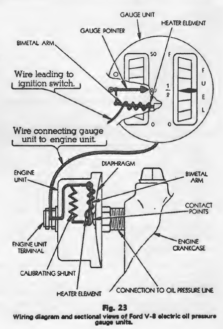
Principle of Operation The oil pressure gauge used in 1935 and 1936 models operates on a thermostatic principle. The diaphragm located 1n the engine unit, Fig. 23, is deflected by the pressure of the oil. As the center of the diaphragm moves away from a vertical plane it makes contact with the bimetal arm in the gauge unit on the dash. One end of the bimetal arm in the gauge unit is attached to the gauge point as shown.
When the diaphragm in the engine unit makes contact with the bimetal arm, an electrical current begins to flow through the gauge circuit. The electrical current
!lowing through the heating elements, wound around the bimetal arms in both the engine and gauge units, causes the arms to be deflected equal amounts. In this
way the amount of oil pressure is recorded by the needle in the gauge unit.
Oil Gauge Failures: Oil gauge failures may be caused by trouble either in the wiring and connections or is the gauge units. To locate trouble, first short the engine unit out by connecting a Jumper wire from the terminal of the engine unit to the frame of the car. Turn on the ignition switch momentarily and if the gauge unit shows a reading, the engine unit will be found to be defective and should be replaced.
Caution: Do not leave the ignition switch turned on too long with the engine unit shorted out because the excessive current load may burn out the element in the gauge unit. If the gauge unit fails to show a reading with the engine
unit shorted out and the ignition switch turned on, inspect the wiring and terminals. If no trouble is found here, replace the gauge unit.
It is not practical to attempt to repair either the gauge or engine units because each unit is calibrated at the factory and cannot be correctly adjusted in the field without the aid of special instruments.