1932-1936 CARBURETORS & FUEL PUMPS
Detroit Lubricator Carburetors
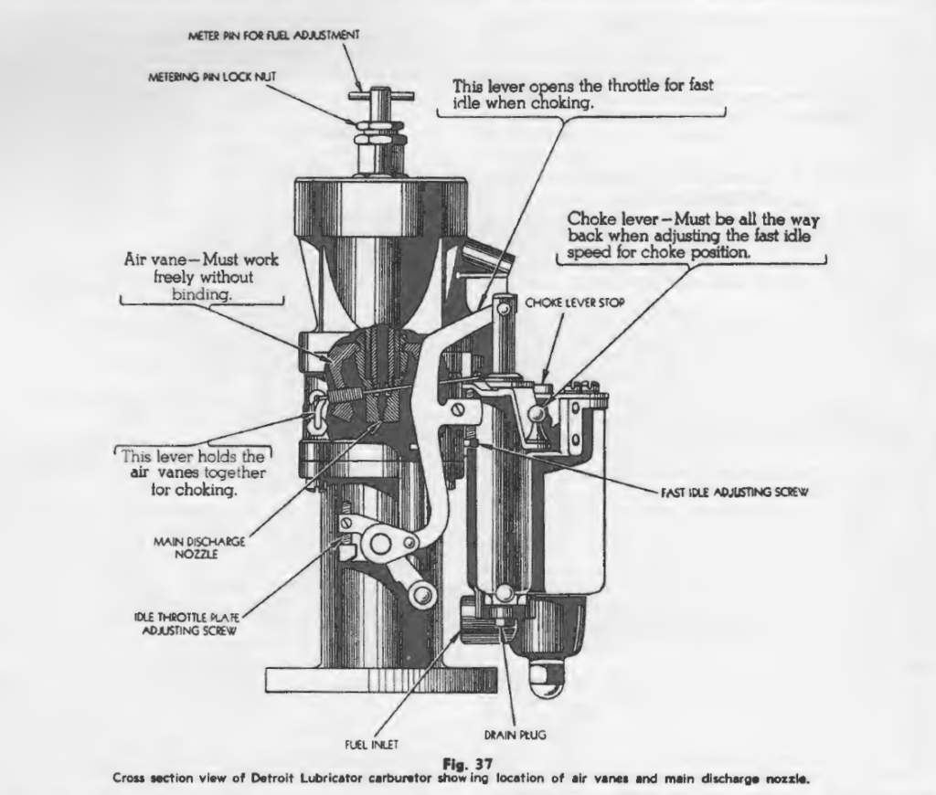
All 1932 and 1933 models were equipped with air vane type, single down draft Detroit Lubricator carburetors as shown in Fig. 37. The air vanes are mounted in the air horn and by means of toggle levers engage a sliding tube containing the main metering orifice. As the speed of the engine is increased the vanes open and the levers slide the tube down away from the metering pin, automatically increasing the fuel supply as the engine is sped up. This device is automatic in its action and requires no adjustment A sluggish engine or excessive fuel consumption may be caused by excessively worn parts or improperly assembled parts. If the carburetor is dismantled for cleaning or repairs be sure to get the vane levers in their proper positions so that they will work freely. If they stick or bind, engine performance may be sluggish or gasoline consumption may be excessive. Parts that are excessively worn should be replaced or the complete carburetor unit exchanged.
How to Adjust the Detroit Lubricator Carburetor: Start the engine and warm it up to normal running temperature. Set the throttle stop screw to idle the engine at a speed equivalent to about six miles per hour. Tum the idle adjusting screw (metering pin for fuel adjustment, Fig. 37) in the center of the air horn, in a clockwise direction until the engine starts to falter, then back it out slowly to the smoothest running position. Lock the adjustment in this position with the lock nut. Reset the throttle stop to the desired idle speed.
The idle speed of the engine can be checked in the following way. Make a chalk mark on the fan belt. Start the engine and count the revolutions. The idling speed will be correct when the fan belt makes about two revolutions per second or averages 20 revolutions every 10 seconds.
Stromberg Carburetors
All 1934. 1935 and 1936 Model A were equipped with dual down draft type EE1 Stromberg carburetors. These carburetors have an idle adjustment only.
Idle Adjustment: Warm the engine up to normal operating temperature. Adjust the throttle stop screw to idle the engine at a speed equivalent to about five or six miles per hour. (The idle speed will be correct at 20 revolutions of the fan belt every 10 seconds).
Turn one idle adjusting screw Fig. 38 in until the engine starts to falter, then back it out slowly until the smoothest operation is obtained. Repeat this operation on the other idle adjusting screw.
After the adjustment has been completed, reset the throttle stop screw to the desired idle speed.
Accelerating Pump: The accelerating pump should have ¾” travel.To check accelerating pump operation, place the carburetor over a container to catch the gasoline from the discharge nozzle. Connect a supply line to the carburetor inlet to keep the gasoline up to the proper level in the float bowl. Pump 10 slow strokes of the accelerating pump by slowly operating the throttle lever the full extent of its travel.
When the pump is working correctly it will pump from 15 to 18 cubic centimeters of gasoline through the pump discharge nozzle with the 10 slow strokes. If it fails to pump this amount, replace the pump inlet check valve assembly and repeat the test. If it still fails to pump the required amount, replace the pump plunger assembly.
If the accelerating pump delivers more than 18 cc. with 10 slow strokes of the plunger, replace the economizer by-pass valve assembly.

Carburetor Specifications
Main Metering Jet Sixes 1934-35-36 Model A:
– Average driving conditions at normal altitudes-.048″:
– Altitudes of 5000 to 10,000 feet-.046″:
– Altitudes of 10,000 to 15,000 feet-.044″;
– Altitude of 15,000 feet or over-.042″.
Float Levels
Detroit Lubricator Carburetors: The float level will be correct when the distance from the top edge of the float bowl to the top of the fuel is 13/16″ plus or minus 1/16″, The float level height is affected principally by wear of
parts only and if found to be wrong can be corrected by replacing the worn parts. Stromberq Type EE Carburetors: To measure the float level for Stromberg EE carburetors, remove the float chamber cover, and start the engine. Adjust the fuel level to 15/32″ below the top of the float bowl with the engine running. The fuel level can be changed by bending the lip of the float lever.
Carburetor Flooding
Stromberg
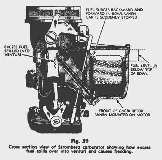
Flooding when the engine stops is most generally caused by interference between the end of the float lever and the carburetor body or a faulty float valve and seat which permits the fuel to be forced past the float valve by the pressure maintained by the fuel pump. Fig. 39 is a sectional view of a Stromberg carburetor showing how excess fuel is spilled into the venturi when the car is suddenly stopped.
To stop flooding, warm the engine up to operating temperature, remove the carburetor cover and allow the engine to idle long enough to establish an operating fuel level in the float bowl. Measure the distance from the top of the bowl to the level of the fuel. Make this measurement a short distance from the side of the carburetor bowl to avoid the curvature of the fuel caused by capillary attraction around the sides of the bowl. Set the level to exactly 1/2″ .. from the machined surface at the top of the bowl by bending the float lever.

After the correct operating fuel level has been established, start the engine and stop it at intervals of two or three minutes to determine whether the level rises in the bowl after the engine is stopped. If the fuel rises in the bowl when the engine is stopped, after the correct fuel level setting has been made, check the clearance between the lip on the end of the float lever and the carburetor body by passing the blade of a feeler gauge between these parts. There
should be not less than .015″ clearance at this point. If too little clearance, use a thinner gasket under the float
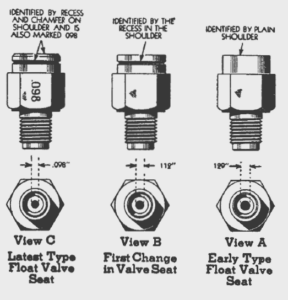
valve seat or cut the end of the lip off to obtain the proper clearance. If there is ample clearance at this point and the float level still rises after the engine has been stopped, obtain a new type float valve and seat and install it in place of the present one. This new float valve assembly is designed to aid in maintaining the proper float level under varying conditions and can be identified by the mark “.098”, View C, Fig. 40 stamped on one side of the hexagon surface
of the valve body. When installing a new float valve and seat it is advisable to install a new type float also which is identified by a punch mark on the lever between the pivot pin hole and the float also shown in Fig. 40. Reset the fuel level after making either of the above repairs.
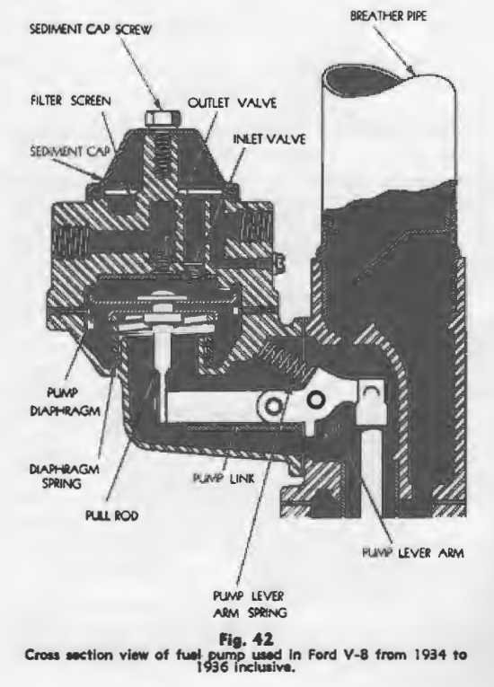
Fuel Pump

Fuel pump failures may be indicated by lack of fuel at the carburetor, excessive gasoline consumption or faulty engine operation and can generally be traced to one of the following causes.
1) Clogged filter screen.
2) Loose connections or an air leak In the supply line.
3) Obstruction In the supply line which restricts the flow of fuel
4) Porous or leaky pump diaphragm-this may result In engine failure on long sustained hard pulls or high speed.
5) Leaky or defective Inlet or outlet valves.
When trouble is experienced with the fuel pump, disconnect the fuel supply line at the pump, remove the gasoline tank cap and blow through the line with compressed air. Tighten all connections and look for leaks in the supply line as a result of chafing. Remove the cover and clean the screen and sediment chamber. Make sure that the gaskets are not broken and are fitted to their seats properly.
Low gasoline mileage or excessive gasoline consumption may be the result of excessive choking when starting which has become necessary as the result of a plugged filter screen or a leaky diaphragm. Remove the pump from the engine and dismantle it completely, Examine the operating levers and replace all worn parts. Install a new set of diaphragms, a new pull rod gasket and make sure that the valves in the upper pump body are seating properly and that the valves are not warped or dirty.
After the above repairs have been completed, mount the pump on the engine. Drain the gasoline out of the carburetor bowl, tum the ignition switch on and start to crank the engine with the starter. If the pump is supplying the correct amount of fuel to the engine, it will prime and start the engine in twenty seconds time.

The fuel pressure between the pump and the carburetor should not be less than 1 ¾ lbs. nor more than 2 1/2. lbs. per sq. in. The fuel pump pressure can be measured on the car with a gauge made up from odd parts as shown in Fig. 43. The necessary measurements for making up this gauge assembly are shown on the cut. To use the pressure gauge, remove the gasoline feed line from the fuel pump to the carburetor and insert the pressure gauge assembly in its place.
Air Cleaners

Filter Type Air Cleaner or Carburetor Silencer: To properly service this type of air cleaner, remove the unit from the engine. Take the felt pad out of the top and plunge the filter element only (see Fig. 44) into gasoline or any good cleaning solvent. Wash it until all dirt and foreign substances have been removed. Dry the unit thoroughly with compressed air and dip the section containing the filter element into clean engine oil. Allow the surplus oil to drain off and replace the unit on the engine.
The felt pad should be examined carefully before replacing it on top of the cleaner. These pads sometimes become ruptured or tom as shown in View A, Fig.44. If these damaged pads are not replaced with new pads, engine performance will be affected at high speeds.
Important: The filter type air cleaner is designed to be installed with the solid portion toward the fan and the cut-away section to the rear of the car. If the cleaner !a not installed in this position, the air blast from the fan will affect the fuel mixture and engine performance will not be satisfactory.
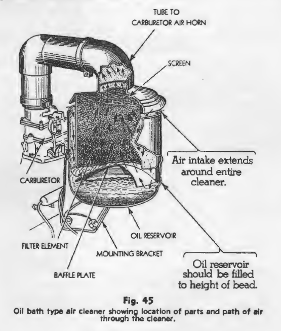
Oil Bath Type Air Cleaner: The oil bath type air cleaner shown in Fig. 45 is designed for use on passenger cars and trucks operating on unpaved roads or under extremely dusty conditions. To service this cleaner, loosen the two wing nuts near the bottom of the unit and remove the oil cup by turning it in a clockwise direction. Empty the old oil out, clean the cup thoroughly and refill to the proper level with clean engine oil. Use S.A.E. No. 30 in summer and S.A.E. No.10 in winter.
After a long period of service under extremely dusty conditions, take the screws out and remove the baffle plate at the bottom of the filter element Tip the screen enough to allow it to come out past the baffle supports Remove the filter element in the same manner and clean these parts thoroughly.
Caution: The oil bath cleaner should be installed on the right side of the carburetor. If installed in any other position the oil level will be affected with the result that fuel consumption would go up and engine performance would be poor.