
1932-1936 Ford Transmissions
Transmission Gear Changes
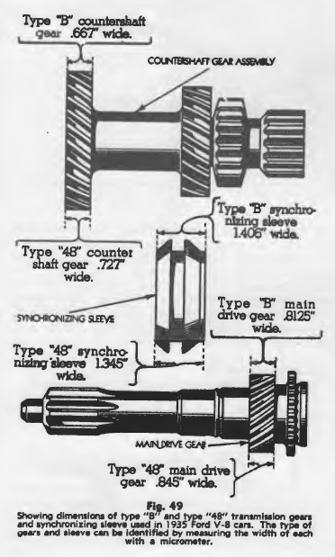
It is important when ordering parts for the 1935 Ford transmission to be sure to specify whether type “B” or type “48” parts are required. These parts are not entirely interchangeable. The early models were equipped with a gear set designated as type “B”, while later models were equipped with a type “48” gear set which can be used in the same transmission case. The difference in the two types of gear sets is found in the difference in the widths of the gears and synchronizing sleeve.
The type “B” counter shaft gear can be used in conjunction with the type “B” synchronizing sleeve only. The type “48” counter shaft gear can be used with the type “48” synchronizing sleeve only. The type “48” counter shaft gear can be used with either the type “B” or the type “48” main drive gear.
The necessary dimensions to identify these parts by type are given in Fig. 49. The measurements should be taken with a micrometer.
Transmission
1932 Passenger Cars Only: The engine and transmission assembly must be removed from the chassis to overhaul the transmission. The fastest procedure for this operation is given as follows:
1) Remove the radiator and front motor support bolts.
2) Disconnect the gasoline line, throttle rods, wiring, exhaust pipes, starting motor cables and other accessories from the engine to clear it from the chassis.
3) Remove the floor boards and take the transmission cover off. 4) Remove the transmission cover and gearshift assembly.
5) Disconnect the rear engine assembly support from the frame cross member at the rear of the transmission, the universal ball cap from the rear of the transmission and the brace rods from the rear of the engine to the frame cross member.
6) Disconnect the front axle radius rods from the under side of the engine.
7) Hook a chainfall on the engine and lift the engine and trans- mission assembly out of the frame. The transmission can now be removed from the engine and dismantled for repairs.
1933, 1934, 1935 and 1936 Passenger Cars Only: The transmission in these models can be removed through the driving compartment without removing the engine by sliding the rear axle assembly back.
1) Disconnect the shock absorber arms from the rear axle, the rear spring from the frame of the car, the rear brake rods from the brake cross shaft and the torque tube ball cap from the rear of the transmission.
2) Raise the body just high enough to clear the wheels. Pull the rear axle assembly back far enough to clear the universal joint and lower the torque tube to the floor.
3) Remove the floor boards, disconnect the service brake rod from the brake pedal and the emergency brake lever from the trans- mission case.
4) Disconnect the bell housing from the engine and the rear sup- port from the frame cross member.
5) Slide the transmission back far enough to clear the clutch hub and lift it out through the driving compartment of the car with the clutch and brake pedals attached.
131″ and 157″ Wheel Base Trucks-All Models: The transmission can be removed from all truck models without removing the engine by the following procedure.
1) Remove the nuts and take out all but the top bolt from the rear universal joint cover flange. The top bolt is left in place. So it will support the rear section of the propeller shaft. Caution: Do not remove it at this time.
2) Detach the front universal joint cover from the rear engine sup- pert and slide it back on the housing far enough to clear the universal joint companion flange.
3) Remove the bolts from the companion flange and separate the joint.
4) Lower the front end of the coupling shaft enough to clear the cross member, pull it forward until the rear universal joint is clear of the propeller shaft and remove the assembly.
5) Remove the detachable frame cross member.
6) Disconnect the brake pedal pull rod.
7) Remove the bell housing bolts. Slide the transmission assembly back far enough to clear the clutch hub and lift it out.
How to Inspect and Test Transmission Parts
Dismantle the transmission and clean the parts thoroughly with gasoline or cleaning solvent.
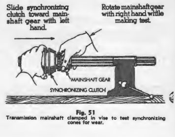
The synchronizing cones can be tested for wear in the following way. Clamp the transmission main shaft in a vise as shown in Fig. 51. Slide the intermediate and high gear clutch sleeve toward the intermediate gear with one hand and at the same time rotate the intermediate gear with the other hand. If the splines in the clutch sleeve contact the ends of the teeth on the hub of the intermediate gear before the cones are engaged sufficiently. To prevent rotating the gear by hand. Observe if the synchronizing cone has been found to be worn to such an extent that the gears will clash when shifting. If so it should be replaced with a new part.
The second speed gear may be removed from the transmission main shaft for inspection by the following procedure.
1) Turn the shaft in the gear until the thrust washer key lock plunger lines up with the hole in the face of the gear.
2) Insert a pin punch through the hole in the face of the gear and press the plunger down far enough to clear the thrust washer key.
3) Start the key out by inserting a screwdriver blade between the splines of the main shaft. Push the key toward the front end of the shaft.
4) Remove the pin punch and continue to push the key forward until it clears the front thrust washer.
5) Turn the thrust washer so that the castellations in the washer line up with the splines on the main shaft and slide the gear and washer off the front end of the shaft.
Inspect the second gear bushing for scores or a galled condition.
Examine the second gear thrust washers each time the gear is removed from the shaft and replace them if they show any indications of wear. Worn thrust washers allow end play in the second gear and may aggravate a condition of slipping out of mesh.
Examine the pilot bearing surface on the front end of the transmission main drive gear or clutch shaft and replace the shaft if the bearing surface is worn enough to permit the bearing cone to spin on the shaft. A loose bearing at this point will result in a noisy or faulty operation of the clutch.
Wash all the grease and grit out of the transmission bearings. Dry them with compressed air and check for rough bearings or worn races. Rough transmission bearings will very often produce noises which may be confused with noises originating in other parts of the car.
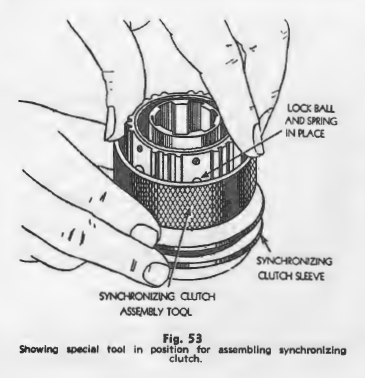
How to Assemble the Synchronizing Clutch
A special tool shown in Fig. 53, should be used in the operation of assembling the springs and balls in the synchronizing clutch. To use the tool, place the outside sleeve of the synchronizing clutch on a level surface and set the assembly tool on the upper surface of the sleeve with the wide part of the taper at the top.
Next, place the six springs and balls in the holes in the clutch hub and slide the assembly down through the tool into the clutch sleeve.
How to Install the Transmission and Engine Assembly
1932 Passenger Cars Only: Bolt the transmission to the engine and swing the whole assembly into position in the chassis so that the support brackets are lined up. Mount by the following procedure.
1) Tighten the rear support bolts to the cross member alternately to avoid pulling the engine out of alignment.
Caution: The rear engine frame to cross member brace rods and front motor supports must be free when the support at the rear of the transmission is being tightened.
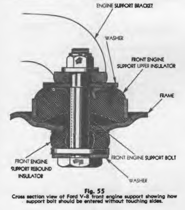
2) Line up the front engine supports so that the support bolts will enter the holes in the engine supports without touching the sides, install the nuts and washers and draw the supports down tight against the shoulder of the support bolts. A cross section view of a front engine support is shown in Fig. 55.
3) Connect the brace rods to the rear of the engine and adjust them so that there is no strain in either direction on either of the rods. Tighten them securely, being careful not to disturb the alignment of the engine.
4) Install the transmission cover and complete the assembly by connecting up the other engine accessories.
1933-34-35-36 Passenger Cars and all Truck Models: The transmissions in these models can be removed without removing the engine. To reinstall the transmission, reverse the removal operations.
Slipping Out of Gear
Slipping out of second gear when going down hill or decelerating is generally caused by wear or looseness in the second gear sliding shaft. If the wear is not excessive the trouble can generally be corrected in the fol- lowing way without removing the transmission.
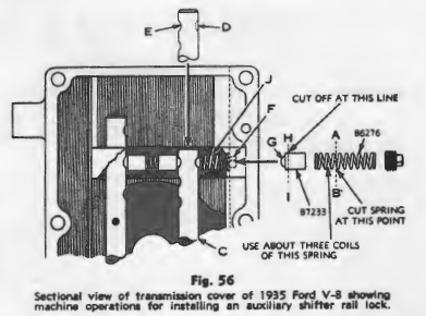
Remove the transmission cover and drive out the pin holding the second gear shift rail in place. Take the rail out of the cover and grind or file a notch in it directly opposite the present second gear notch as shown in Fig. 56. The new notch should fit the contour of the shift lock ball. Reassemble the rail to the cover.
Obtain an extra shift lock ball and spring and cut the shift lock off as shown at HI. Next, cut three coils off the spring as shown at AB. Remove the plug F and insert the extra shift lock ball and spring in the plug hole. This extra shift lock ball will serve as an auxiliary second gear shift rail lock and will prevent the second gear slipping out of mesh.